
More project photos (2)
The problem
Rotating machines — motors, pumps, fans — rarely fail without warning: rising vibration is usually the earliest sign of imbalance, misalignment or bearing wear. In industry this is tracked with expensive vibration analyzers and predictive-maintenance software, but students typically only read about FFT spectra and ISO 10816 zones in textbooks and never implement the chain themselves. This project closes that gap by building a complete, low-cost condition-monitoring loop on an ESP32: a 3-axis ADXL345 accelerometer samples vibration at a 200 Hz design target, the ESP32 computes a 1024-point FFT on the device to separate 1× running speed from its harmonics and bearing tones, and RMS velocity is checked against configurable warning and critical thresholds. Results stream over Wi-Fi to a live dashboard showing the time-domain waveform, the FFT spectrum with marked harmonics, and an alert event log. Because the thresholds are calibrated by the buyer on their own hardware, every number the student reports comes from their own build.
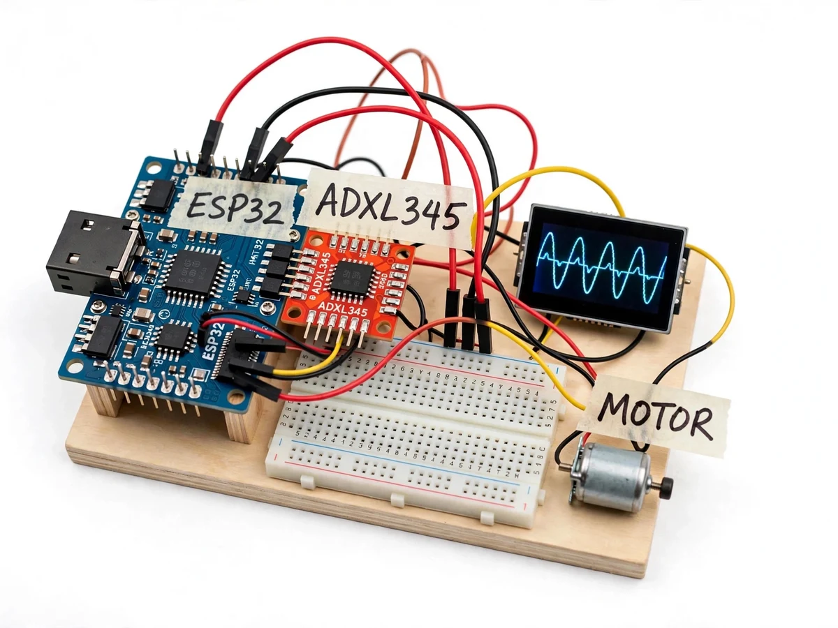
MEMS accelerometer rigidly mounted on the machine body; samples X, Y, Z over I2C at 200 Hz.
Follow the working sequence
How it works
- The ADXL345 accelerometer is rigidly mounted on the motor or machine body; the ESP32 samples the three axes over I2C at 200 Hz (design target).
- Each sampling window is windowed (Hanning) and passed through a 1024-point FFT on the ESP32, yielding the vibration spectrum from 0 to 100 Hz.
- Firmware computes overall RMS velocity (integrated from acceleration, configurable frequency range), finds the dominant frequency, and compares it with the expected running speed derived from the motor's rated RPM.
- The RMS velocity and selected harmonic amplitudes are checked against the warning and critical thresholds; persistence logic (threshold crossed for N consecutive windows) filters out single-window spikes before an alert is raised.
- On a confirmed alert the node updates its OLED status, sounds the buzzer if critical, and pushes the event with timestamp to the dashboard's alert log over Wi-Fi.
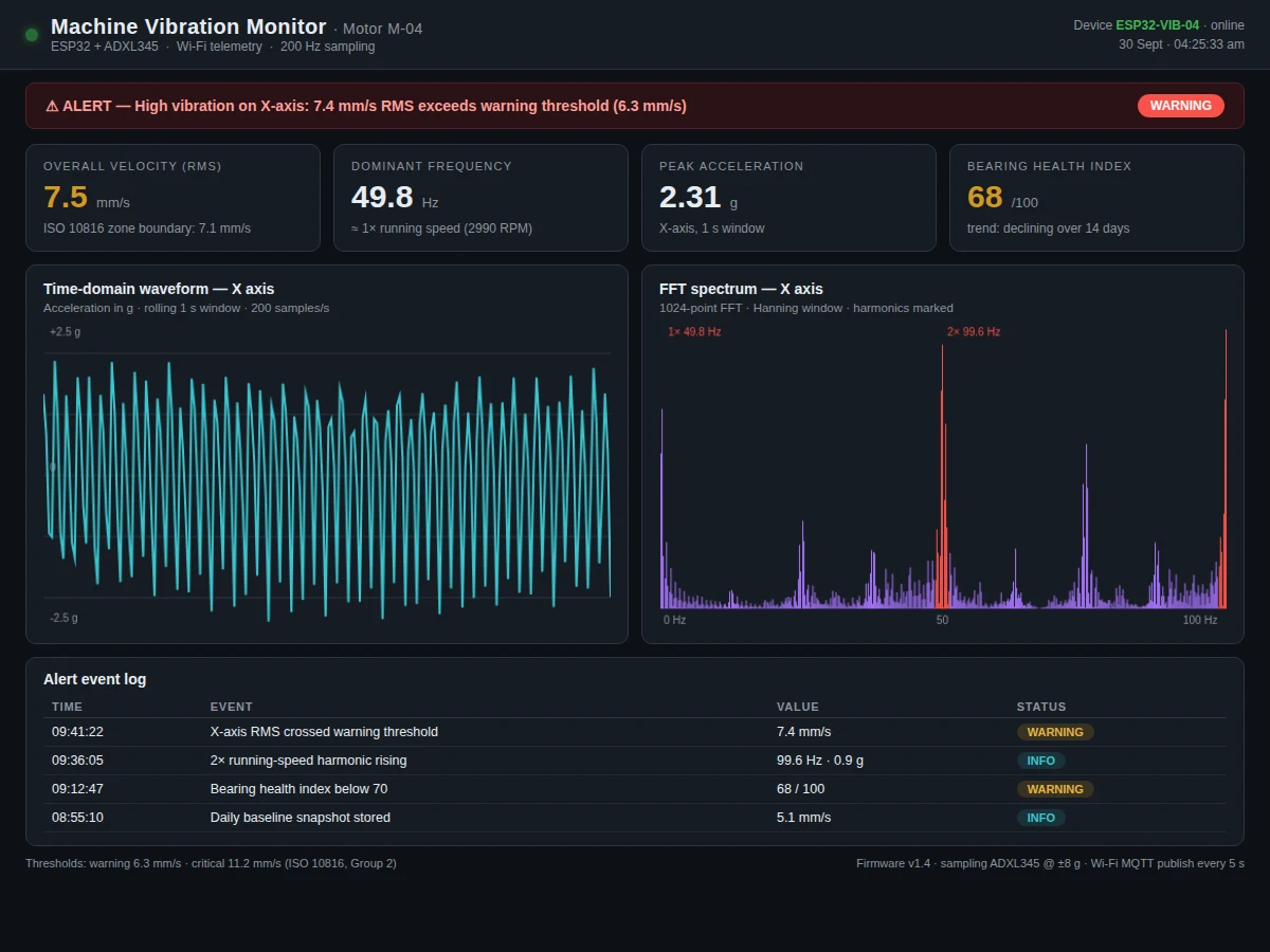
- The dashboard renders the rolling waveform, the spectrum with marked 1×/2× peaks, and trend cards, while the event log records every threshold crossing for the report.
Tech stack:
- ESP32 development board (dual-core Xtensa, Wi-Fi)
- ADXL345 3-axis accelerometer · I2C
- 1024-point FFT on-device · arduinoFFT-style fixed-point
- 0.96-inch OLED display (on-node status)
- Buzzer (local critical alarm)
- Single-file web dashboard · HTML/CSS/JS, canvas charts
- MQTT / HTTP telemetry over Wi-Fi
- Arduino IDE (C/C++ firmware)
| Parameter | Value |
|---|---|
| Accelerometer | ADXL345, 3-axis MEMS (datasheet: ±16 g max range, 13-bit resolution) |
| Sampling rate | 200 Hz per axis (design target, I2C interface) |
| FFT | 1024-point, Hanning window, on-device (design target) |
| Spectrum range | 0–100 Hz (Nyquist at 200 Hz sampling) |
| Velocity metric | RMS velocity, mm/s, integrated from acceleration (design target) |
| Warning threshold | 6.3 mm/s RMS (configurable design default) |
| Critical threshold | 11.0 mm/s RMS (configurable design default) |
| Telemetry | Wi-Fi MQTT/HTTP publish every ~5 s (design target) |
| On-node display | 0.96-inch OLED: RMS, dominant frequency, alert state |
| Test rig | Small DC motor with optional imbalance weight for demo (design) |
Project features
- [3-axis vibration sensing] An ADXL345 MEMS accelerometer (±16 g range, 13-bit resolution per datasheet) mounted on the machine body samples acceleration on X, Y and Z axes over I2C.
- [On-device FFT analysis] A 1024-point FFT computed on the ESP32 produces the vibration spectrum, with the 1× running-speed peak and its 2× harmonic identified and marked for the dashboard.
- [Predictive-maintenance alert thresholds] Configurable warning (6.3 mm/s) and critical (11.0 mm/s) RMS velocity thresholds in the ISO 10816 style, with per-harmonic watch bands for misalignment and bearing tones.
- [Live companion dashboard] A single-file web dashboard shows the rolling time-domain waveform, the FFT spectrum with marked harmonics, KPI cards (RMS velocity, dominant frequency, peak acceleration, bearing health index) and the alert event log.
- [On-device status display] A small OLED on the node shows current RMS velocity and NORMAL / WARNING / CRITICAL state, so the hardware is demonstrable without the dashboard.
- [Buzzer alarm output] A local buzzer sounds when a critical threshold is confirmed, giving the node a standalone alarm behavior for lab demos.
- [Wi-Fi telemetry] RMS velocity, dominant frequency, alert state and event log entries publish over Wi-Fi (MQTT/HTTP) to the dashboard every 5 seconds as a design target.
- [Buyer-run calibration procedure] A documented procedure guides the student to measure their machine's healthy baseline and set the warning/critical thresholds for their specific rig.
What is included
- Assembled sensor-node prototype (ESP32 + ADXL345 + OLED + buzzer, wired on base)
- ESP32 firmware source (sampling, FFT, threshold logic, telemetry, OLED UI)
- Companion live dashboard (single-file HTML/CSS/JS, works on the local network)
- Wiring diagram and mounting guidance for the accelerometer
- Buyer-run baseline and threshold-calibration procedure
- Project report PDF (vibration theory, FFT, ISO 10816 zones, methodology, results from your own readings)
- PPT presentation for final review
- Viva Q&A preparation document (FFT, aliasing, Nyquist, RMS vs peak, threshold logic)
Limitations & prerequisites
- The 200 Hz sampling rate gives a 0–100 Hz spectrum — high-frequency bearing tones above ~100 Hz are out of scope; this is stated in the report and follows the Nyquist limit, not a measured claim.
- The demo rig is a small DC motor, not an industrial machine — the ISO 10816-style thresholds are adapted teaching values; the report explains the scaling honestly.
- RMS velocity is derived by integrating acceleration in firmware; DC offset and low-frequency noise are filtered, and the procedure documents the buyer-measured noise floor.
- Wi-Fi telemetry needs the node and the viewing device on the same local network — no remote cloud, SMS or GPS alerting is in the build.
- Alert accuracy depends on the student-calibrated thresholds; there is no claim of detecting faults the student has not demonstrated on their own rig.
- This is a teaching prototype, not certified condition-monitoring equipment — not for safety-critical or production machinery decisions.
Frequently Asked Questions
Why an ESP32 instead of an Arduino?
The FFT needs real compute — 1024 points every window plus Wi-Fi telemetry. The ESP32's dual-core processor and built-in Wi-Fi handle both, while an Uno-class board would struggle with the FFT at these window sizes.
What does the FFT actually show?
It converts the vibration waveform into a spectrum: the height of each peak shows how much energy exists at that frequency. The 1× peak sits at the motor's running speed; a growing 2× peak hints at misalignment and rising high-frequency tones hint at bearing wear — the classic pattern the dashboard marks.
How are the alert thresholds set?
The firmware ships with configurable defaults (6.3 / 11.0 mm/s, adapted from ISO 10816 teaching practice). The included calibration procedure has the buyer measure their own motor's healthy baseline first, then set the thresholds relative to it — so the alert numbers in the report are the student's own measurements.
Can it really predict maintenance needs?
It detects the vibration signatures that precede failures — rising overall RMS and growing fault harmonics — which is exactly what predictive-maintenance monitoring does at teaching scale. The report is careful: the system flags vibration conditions, it does not diagnose specific faults without the student's own analysis.
Does it need the internet?
No — the node and dashboard communicate over the local Wi-Fi network. No cloud account, no SMS and no GPS are part of the build, which keeps the demo working in a lab without internet.
Is this project suitable for a final-year project?
Yes — for IoT, Embedded Systems and Electronics programs. It demonstrates sensor interfacing, real-time signal processing (FFT), threshold-based alert logic, Wi-Fi telemetry and a live dashboard — a complete hardware-to-software loop. Suitable for B.E./B.Tech final-year projects in IoT, Embedded Systems and Electronics engineering. problem: Bearings, imbalance and misalignment are among the earliest precursors of rotating-machine failure, and rising vibration is their most accessible symptom. Industrial condition monitoring uses expensive analyzers and software that students never get to operate, so final-year students learn FFT spectra, aliasing and ISO 10816 zones only as theory. This project gives them the full chain to build and demonstrate themselves: a low-cost ESP32 + MEMS accelerometer node that samples vibration, computes the spectrum on-device, and raises threshold-based predictive-maintenance alerts streamed live to a dashboard. concept: An ADXL345 accelerometer mounted on the machine body feeds 3-axis vibration data to an ESP32 over I2C at a 200 Hz design target. Each window is Hanning-windowed and transformed with a 1024-point FFT on the device, producing a 0–100 Hz spectrum from which the firmware extracts RMS velocity, the dominant frequency, and the 1×/2× running-speed harmonics. These metrics are compared against configurable warning and critical thresholds with persistence filtering; confirmed alerts update the on-node OLED, sound the buzzer on critical, and push timestamped events over Wi-Fi (MQTT/HTTP) to a companion dashboard that renders the live waveform, marked FFT spectrum, KPI cards and an alert event log. A buyer-run calibration procedure sets thresholds from the student's own baseline measurements. features:
- ADXL345 3-axis MEMS accelerometer sampling over I2C at 200 Hz (design target)
- 1024-point on-device FFT with Hanning window; 0–100 Hz spectrum
- 1× running-speed and 2× harmonic identification and dashboard marking
- Configurable warning (6.3 mm/s) and critical (11.0 mm/s) RMS velocity thresholds
- Persistence filtering so single-window spikes do not raise alerts
- Companion live dashboard: waveform, FFT spectrum, KPI cards, alert event log
- On-node 0.96-inch OLED status display (NORMAL / WARNING / CRITICAL)
- Local buzzer alarm on confirmed critical alert
- Wi-Fi telemetry (MQTT/HTTP) to dashboard every ~5 s (design target)
- Buyer-run baseline and threshold-calibration procedure requirements:
- ESP32 development board with Wi-Fi
- ADXL345 3-axis accelerometer breakout (I2C)
- 0.96-inch OLED display (I2C)
- Active buzzer module, jumper wires, breadboard or base
- Small DC motor test rig with optional imbalance weight (demo)
- Computer with Arduino IDE for firmware; any modern browser for the dashboard
- Local Wi-Fi network for node-to-dashboard telemetry (no internet required) deliverables:
- Assembled sensor-node prototype (ESP32 + ADXL345 + OLED + buzzer)
- ESP32 firmware source with comments (sampling, FFT, thresholds, telemetry, OLED UI)
- Companion live dashboard (single-file HTML/CSS/JS)
- Wiring diagram and accelerometer mounting guidance
- Buyer-run baseline and threshold-calibration procedure
- Abstract + project report PDF (theory, methodology, student's own readings)
- PPT presentation for final review
- Viva Q&A preparation document limitations:
- 0–100 Hz spectrum only (200 Hz sampling → Nyquist limit); high-frequency bearing tones above ~100 Hz out of scope
- Demo rig is a small DC motor — thresholds are teaching values adapted from ISO 10816 practice, not industrial certification levels
- RMS velocity is integrated from acceleration in firmware; buyer measures their own noise floor per the procedure
- Wi-Fi telemetry is local-network only; no cloud, SMS or GPS in the build
- Alert quality depends on student-calibrated thresholds; no claim of diagnosing faults not demonstrated on the student's rig
- Teaching prototype, not certified condition-monitoring equipment timeline:
- Typical built-to-order delivery: hardware assembly and wiring in the first week, firmware (sampling, FFT, threshold logic) in the second, dashboard and report documentation in the third, with the calibration procedure run and verified on the finished build before handover. Exact schedule is confirmed at order time. support:
- Explanation support covers the full chain: ADXL345 interfacing, FFT and windowing choices, RMS integration, threshold and persistence logic, and the dashboard telemetry flow — so the student can answer viva questions on every part. Report, PPT and viva Q&A are included; code walkthrough provided on request.
Components & software requirements
- ESP32 development board (dual-core Xtensa, Wi-Fi)
- ADXL345 3-axis accelerometer · I2C
- 1024-point FFT on-device · arduinoFFT-style fixed-point
- 0.96-inch OLED display (on-node status)
- Buzzer (local critical alarm)
- Single-file web dashboard · HTML/CSS/JS, canvas charts
- MQTT / HTTP telemetry over Wi-Fi
- Arduino IDE (C/C++ firmware)
Delivery information
Built-to-order project. Delivery timeline is shared after order confirmation based on current queue.
Support terms
Complete documentation, setup guide, and viva preparation included. Support for setup and explanation provided.
Download free synopsis (PDF)
Enter your name and email — the synopsis PDF downloads immediately. We may send occasional project updates; no spam, unsubscribe anytime.