
More project photos (2)
The problem
A UPS is the one device everyone ignores until the power fails — and then discovers the battery died months ago. Offices lose unsaved work and routers drop because nobody knew the backup time had degraded to minutes. The failure is not the UPS; it is the absence of visibility. This project adds that visibility as a non-invasive monitor: an ESP32 node senses mains presence, battery terminal voltage and load current, derives charging/discharging state and state-of-charge trend, and estimates remaining backup time from the live load. All of it streams to a purpose-built web dashboard — battery gauge, backup-time readout, mains/battery state timeline, and a log of every power event. The hardware is the sensing node; the software is the dashboard, and both are built for this project.
How it works
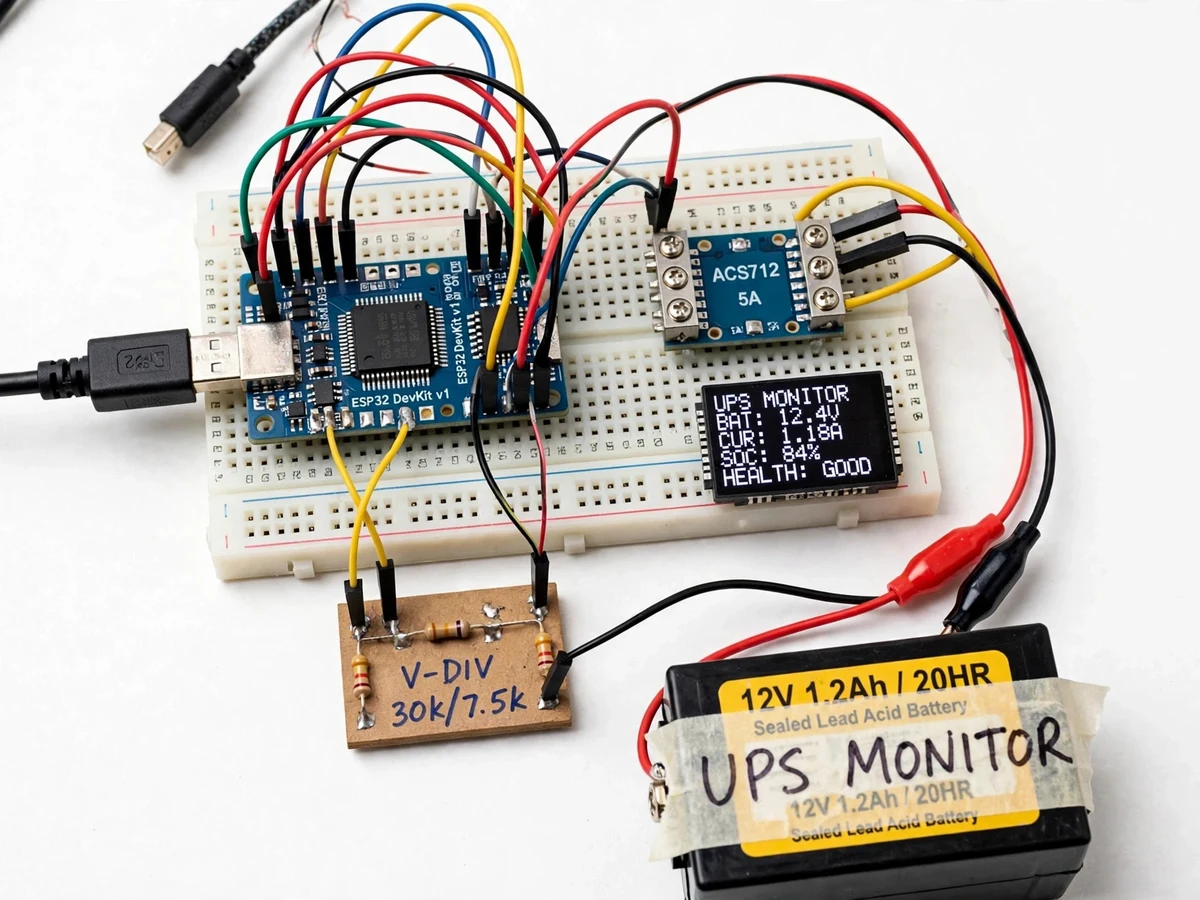
- The ESP32 node connects isolated sense leads to the mains input, the battery terminals and a current sensor on the UPS output.
- Firmware samples voltage and current, classifies the operating state (mains present, charging, on-battery, battery low), and estimates backup time from battery voltage and live load.
- Readings publish over Wi-Fi (MQTT/HTTP) every few seconds to the cloud backend feeding the web dashboard.
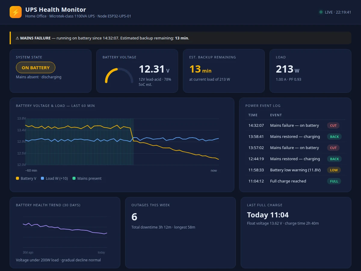
- The dashboard renders the battery gauge, backup-time readout, state timeline, voltage history chart and the timestamped power-event log.
- Crossing the low-battery or long-outage thresholds triggers phone/push alerts to the owner.
- Long-term voltage-under-load curves accumulate in history, letting the owner spot battery degradation trends.
- The student calibrates the voltage sense channels against a multimeter with the included procedure so dashboard readings match reality.
Tech stack:
- ESP32 development board (Wi-Fi)
- Isolated mains-presence sensing + battery voltage dividers
- Hall/ACS-class current sensor on UPS output
- 0.96-inch OLED (local status at the node)
- Arduino IDE (C/C++ firmware)
- MQTT/HTTP telemetry to cloud backend
- Single-file HTML/CSS/JS dashboard (Chart.js-style gauges and charts)
- Push alerts (Blynk/ThingSpeak class)
| Parameter | Value |
|---|---|
| Monitored UPS | Single-phase home/office UPS or inverter, 12 V battery class (design) |
| Sensed quantities | Mains presence, battery voltage, load current (design) |
| Backup-time estimate | From live load + battery voltage trend, updates continuously (design target) |
| Publish interval | Approximately every 5 s (design target) |
| Dashboard | Single-file web app: gauges, charts, event log (built for this project) |
| Alerts | Low-battery + long-outage push alerts (design) |
| Local display | OLED: state + backup time (design) |
| Calibration | Buyer-run multimeter comparison procedure included |
Project features
- [Mains and battery sensing] Isolated sensing of mains presence, battery terminal voltage and load current gives the node everything needed to judge UPS health without opening the UPS.
- [Backup-time estimation] Firmware combines battery voltage trend with live load current to estimate remaining backup time, shown as a prominent dashboard readout that updates as load changes.
- [Charge/discharge state tracking] The node classifies MAINS / CHARGING / ON BATTERY / BATTERY LOW states and the dashboard renders them as a live status timeline.
- [Power-event log] Every mains failure and restoration is timestamped and logged, so the owner can see outage history and the dashboard can flag unusually long outages.
- [Battery-health trend] Long-term battery voltage curves under load reveal a degrading battery weeks before it fails a real outage — the dashboard keeps this history.
- [Low-battery and long-outage alerts] Phone/push alerts fire when backup time drops under the configured threshold or the mains stay down beyond the set duration.
- [Working web dashboard] A single-file HTML/CSS/JS dashboard with gauges, charts and the event log — built for this project and screenshotted for the listing gallery.
What is included
- ESP32 UPS sensing node with isolated sense inputs and OLED
- Current sensor and battery/mains sense wiring kit
- Firmware with state classification and backup-time estimation
- Working single-file web dashboard (gauges, charts, event log)
- Cloud telemetry + alert setup guide
- Buyer-run voltage calibration procedure
- Project report PDF (sensing design, backup-time method, methodology)
- PPT presentation for final review
- Viva Q&A preparation document (battery behaviour, sensing isolation, IoT pipeline)
Limitations & prerequisites
- The monitor observes the UPS externally; it cannot change UPS charging behaviour or revive a dead battery.
- Backup-time estimation is approximate — it depends on battery age, temperature and load type, and must be validated by the student with a timed discharge test.
- Battery-health trending needs weeks of history to be meaningful; a fresh install shows only instantaneous state.
- Voltage sense channels must be calibrated against a multimeter; uncalibrated readings are indicative only.
- The node needs continuous Wi-Fi for live dashboard data; the local OLED keeps working regardless.
Frequently Asked Questions
How does it estimate backup time?
From the battery's terminal voltage trend combined with the measured load current: firmware maps the live operating point against the battery's discharge behaviour and updates the estimate as the load changes.
Does it work with any UPS?
It is designed for common single-phase home/office UPS and inverter units with a 12 V battery; the sense leads are external and isolated, so the UPS itself is not modified.
What does the dashboard show?
A battery gauge, live backup-time readout, mains/battery state timeline, battery-voltage history chart, load chart and a timestamped log of every power cut and restoration.
How will I know the battery is degrading?
The dashboard keeps long-term voltage-under-load curves; a battery that sags faster than it used to is visibly degrading weeks before it fails an outage.
Is the backup-time figure exact?
No — it is an estimate, honestly labelled. Battery age, temperature and load type all shift it, and the report includes a timed-discharge validation procedure the student runs.
Is this project suitable for a final-year project?
Yes — for IoT, Embedded and Electrical programs. It combines isolated sensing, embedded state estimation and a complete working dashboard in one demonstrable system. Suitable for B.E./B.Tech final-year projects in IoT, Embedded Systems and Electrical engineering.
Components & software requirements
- ESP32 development board (Wi-Fi)
- Isolated mains-presence sensing + battery voltage dividers
- Hall/ACS-class current sensor on UPS output
- 0.96-inch OLED (local status at the node)
- Arduino IDE (C/C++ firmware)
- MQTT/HTTP telemetry to cloud backend
- Single-file HTML/CSS/JS dashboard (Chart.js-style gauges and charts)
- Push alerts (Blynk/ThingSpeak class)
Delivery information
Built-to-order project. Delivery timeline is shared after order confirmation based on current queue.
Support terms
Complete documentation, setup guide, and viva preparation included. Support for setup and explanation provided.