
More project photos (2)
The problem
Hot water for bathing and washing is one of the most electricity-hungry loads in a household, and solar water heating is a mature, proven answer — but flat-plate systems lose a lot of heat on windy or cold mornings, which is exactly why commercial heaters moved to evacuated tubes. Most mechanical students can quote "thermosiphon" in a viva yet have never designed the loop, sized a collector, or measured a collector efficiency curve themselves. This project closes that gap with a compact, college-buildable unit: a 12-tube evacuated-tube collector, a fabricated manifold, and a 100 LPD insulated tank mounted above it so water circulates purely by buoyancy. The student designs the stand for the site's latitude, instruments inlet and outlet temperatures, and computes thermal efficiency from real logged data using m·cp·ΔT against incident solar radiation.
Solar irradiance trapped by the selective absorber layer inside each evacuated tube.
Follow the working sequence
How it works
- Each evacuated tube traps sunlight in its selective absorber layer; the vacuum annulus between the inner and outer glass stops convective heat escaping to the air.
- Heat conducts into copper fin/U-pipe elements that carry the system water along the tube; water inside the hot tubes drops in density as it warms.
- The stand tilts the collector at approximately the site latitude plus 10°, facing true south, for year-round irradiance capture.
- Warmer water rises through the manifold into the tank bottom, while cooler denser water from the tank sinks into the collector — a self-sustaining thermosiphon loop with zero electrical input.
- Hot water stratifies at the top of the 100 LPD insulated tank; evening draw-off comes from the hot leg while cold makeup water enters at the bottom.
- During testing, inlet and outlet thermocouples record a ΔT of typically 30–45 °C across the collector on a clear day.
- Daily efficiency is calculated as (m·cp·ΔT)/(A·G·t) — logged water mass, temperature rise, collector area and measured solar radiation — with 60–75% as the expected range for a sound build.
Tech stack:
- Borosilicate evacuated tubes 58 mm × 1800 mm (datasheet size)
- Stainless-steel tank, 100 LPD, PUF insulated
- Copper piping + brass fittings
- Galvanized mild-steel angle stand
- K-type thermocouples (2 channels)
- Insulation: 50 mm PUF + outdoor cladding
- Hand-drawn fabrication drawings / CAD
- Test logging sheets + efficiency workbook
| Parameter | Value |
|---|---|
| Storage capacity | 100 LPD (design choice) |
| Collector tubes | 12 nos., 58 mm OD × 1800 mm (datasheet) |
| Absorber area | Approximately 1.25 m² (design choice) |
| Collector tilt | Site latitude + 10° (installation setting) |
| Tank elevation above manifold | ≥300 mm (installation rule) |
| Tank insulation | Approximately 50 mm PUF (design target) |
| Expected outlet ΔT (clear day) | 30–45 °C rise (expected) |
| Expected daily efficiency | 60–75% (expected, not a measured claim) |
| Expected overnight temperature drop | ≤5 °C (expected) |
| Unit footprint | Approximately 1.2 m × 1.6 m (approximate) |
| Cold-in / hot-out ports | 15 mm threaded (standard) |
Project features
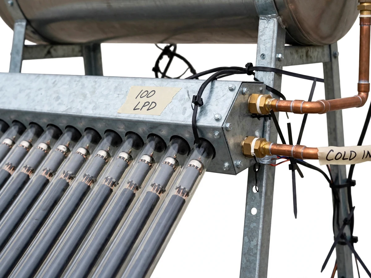
- [12-tube evacuated-tube collector] Twelve borosilicate tubes (58 mm OD × 1800 mm length, standard datasheet size) with selective absorber coating — far lower convective loss than a flat plate, so the unit still delivers hot water on cool mornings.
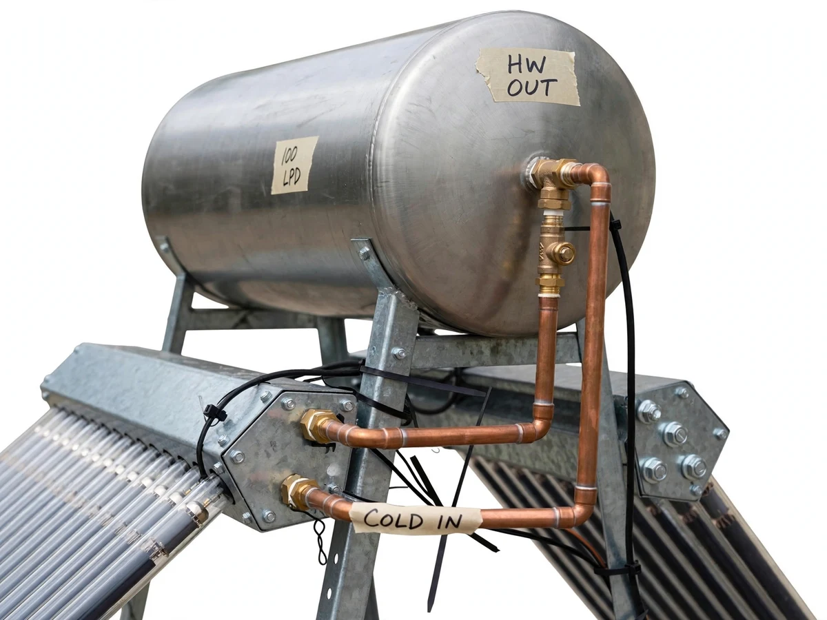
- [Passive thermosiphon loop] The 100 LPD tank sits at least 300 mm above the manifold top, so heated water rises and cool water sinks by density difference alone — no pump, no power, no moving parts to fail.
- [Insulated 100 LPD storage tank] Stainless-steel inner tank wrapped in approximately 50 mm polyurethane-foam insulation, holding the day's heat for evening use with an expected overnight drop of under 5 °C.
- [Latitude-matched stand] A galvanized angle-iron stand fabricated for the site's latitude plus 10° tilt and true-south orientation, with the slope geometry shown on the fabrication drawing.
- [Instrumented test procedure] Two calibrated thermocouples (collector inlet and outlet) plus a pyranometer-hour log sheet, so inlet/outlet ΔT and solar radiation are recorded honestly for the efficiency calculation.
- [Copper manifold with isolation valves] Brass elbows, a gate valve on the hot leg and a drain cock at the lowest point — the unit can be isolated, drained and serviced like real installed systems.
- [Fabrication drawings and BOM] Full dimensioned drawings of the stand, manifold and tank cradle with a bill of materials using locally available sizes, so the viva covers build decisions, not just theory.
What is included
- Fabricated 12-tube collector with manifold and mounting stand
- 100 LPD insulated stainless-steel storage tank with stand cradle
- Copper piping, brass elbows, gate valve and drain cock
- Masking-tape style port labeling on tank and pipes
- Dimensioned fabrication drawings and bill of materials
- Test procedure with thermocouple positions and logging sheets
- Project report PDF (background, thermosiphon theory, sizing calculations, test method, results)
- PPT presentation for final review
- Viva Q&A preparation document (thermosiphon, evacuated tubes, efficiency calculation, losses)
Limitations & prerequisites
- Hot-water output depends entirely on sunlight — heavy cloud cover reduces ΔT and may leave the tank lukewarm; there is no electric backup heater in this build.
- The 60–75% efficiency figure is an expected range, stated honestly — the report documents the efficiency the student's own test run actually measures.
- Thermosiphon requires the tank above the collector and unobstructed roof space; it cannot be mounted on a wall below the collector line.
- Overnight standby losses exist despite insulation — a ≤5 °C drop is expected, and longer draws cool the tank faster than the collector can recharge it.
- Water quality matters: hard or saline water scales the copper tubes faster; no filtration stage is included.
- The unit is a teaching prototype, not a certified commercial heater — no ISI/BIS certification is claimed.
Frequently Asked Questions
How does the thermosiphon loop actually move the water?
When water in the collector tubes heats up, it becomes less dense and rises through the manifold into the tank, while cooler, denser water sinks down into the collector to take its place. The tank sits at least 300 mm above the manifold so gravity separates the two columns. The circulation runs continuously in daylight with no pump and no electricity — and that density-driven loop is the part examiners probe hardest.
Why evacuated tubes instead of a flat-plate collector?
The vacuum annulus between the two glass layers of each tube blocks convective and conductive heat loss to the surrounding air, so the absorber stays hot even on windy or cool mornings when a flat plate bleeds heat. That is why evacuated-tube systems dominate residential installations, and it gives the project a real performance argument backed by the measured efficiency test.
Is the 60–75% efficiency a guaranteed figure?
No — it is an expected range for a well-built thermosiphon unit, not a measured claim. The project includes a proper test procedure (inlet/outlet thermocouples, logged solar radiation, m·cp·ΔT over aperture area), and the report records whatever the test actually shows, with the analysis explaining any shortfall honestly.
What does the student actually build versus buy?
The stand, manifold, tank cradle, piping runs and insulation are fabricated; the evacuated tubes, thermocouples, valves and tank shell material are procured. The student's design work is the collector sizing, the thermosiphon height layout, the tilt geometry and the efficiency calculation — all of which are defended in the viva.
Is this project suitable for a final-year project?
Yes — for Mechanical Engineering programs. It combines heat-transfer theory, fabrication, instrumentation and real measured results, and the thermosiphon analysis plus efficiency calculation gives solid, quantifiable viva material.
Components & software requirements
- Borosilicate evacuated tubes 58 mm × 1800 mm (datasheet size)
- Stainless-steel tank, 100 LPD, PUF insulated
- Copper piping + brass fittings
- Galvanized mild-steel angle stand
- K-type thermocouples (2 channels)
- Insulation: 50 mm PUF + outdoor cladding
- Hand-drawn fabrication drawings / CAD
- Test logging sheets + efficiency workbook
Delivery information
Built-to-order project. Delivery timeline is shared after order confirmation based on current queue.
Support terms
Complete documentation, setup guide, and viva preparation included. Support for setup and explanation provided.
Download free synopsis (PDF)
Enter your name and email — the synopsis PDF downloads immediately. We may send occasional project updates; no spam, unsubscribe anytime.