
More project photos (2)
The problem
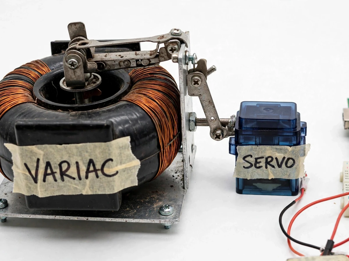
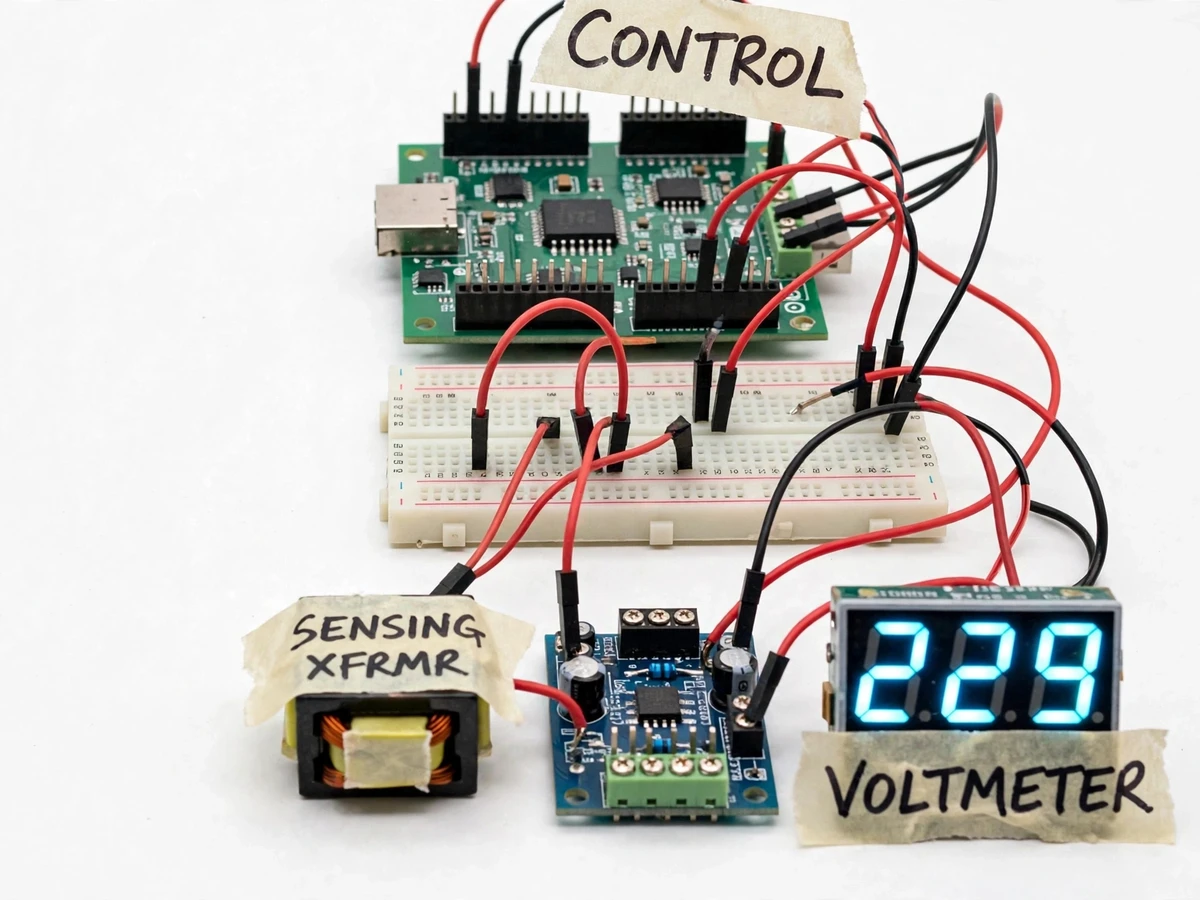
Mains voltage in many areas drifts well above or below the nominal 230 V, and sensitive loads — motors, pumps, lab instruments — suffer from both sags and swells. The common home stabilizer fixes this with a relay that switches between transformer taps, which corrects only in steps and produces a small jump every time it changes taps. A servo-variac stabilizer works differently: it moves a carbon brush wiper along a continuously wound transformer coil, so the correction is smooth. This project builds that continuous stabilizer from real parts — a toroidal variac, a servo motor coupled to its shaft, a microcontroller reading the mains through an isolated sensing transformer, and a digital voltmeter display. The student gets hands-on experience with mains sensing, closed-loop control, mechanical coupling and the dead-band design that keeps the servo from oscillating. It is a strong electrical-engineering project because every part of the control loop is visible and measurable on the bench.
How it works
- The step-down sensing transformer reduces the mains voltage to a few volts AC; a rectifier and filter convert it to a DC signal proportional to the mains voltage.
- The microcontroller samples this signal on its ADC, averages several readings to reject noise, and converts it back to the equivalent mains voltage.
- The firmware compares the measured voltage with the 230 V set point. If the error is outside the ±3 V dead-band (design choice), the controller steps the servo toward correction.
- The servo rotates the variac wiper along the winding; because the wiper moves continuously, the output voltage rises or falls smoothly rather than jumping between taps.
- Once the measured voltage settles inside the dead-band, the firmware starts a 1-second settle delay and then stops driving the servo, preventing hunting oscillation.
- The digital voltmeter module continuously displays the output voltage, giving a live read-out of the loop's performance.
- The control loop repeats every few hundred milliseconds (design target), tracking slow mains drifts without reacting to brief noise spikes.
Tech stack:
- Arduino-compatible microcontroller board
- Toroidal variac (variable auto-transformer)
- RC servo motor with mechanical coupling linkage
- Step-down sensing transformer
- Rectifier and filter stage
- Digital voltmeter module (LED display)
- Relay module (optional protection stage)
- Arduino IDE firmware (C++)
| Parameter | Value |
|---|---|
| Output voltage set point | 230 V AC (design target) |
| Correction type | Continuous servo-variac (smooth, not stepped) |
| Dead-band | ±3 V (design choice — see build notes) |
| Settle delay | Approximately 1 second (design choice) |
| Control loop interval | Approximately 300–500 ms (design target) |
| Variac rating | Approximately 0–270 V, 2 A class (datasheet value) |
| Servo travel | Approximately 180° rotation (datasheet value) |
| Voltmeter range | 0–500 V AC (datasheet value) |
| Mains input | 230 V AC nominal, 50 Hz |
Project features
- [Continuous servo-variac correction] The servo rotates the variac wiper along the winding, so output voltage adjusts smoothly instead of jumping between fixed relay taps — the core engineering contrast this project demonstrates.
- [Microcontroller closed-loop control] The controller reads the stepped-down, rectified mains voltage on its ADC, compares it against the 230 V set point, and drives the servo in the correcting direction until the error falls inside the dead-band.
- [Dead-band and settle delay] Build note from the prototype: the servo hunts if the dead-band is narrower than ±2 V, so the build uses a ±3 V dead-band plus a 1-second settle delay — the output holds rock-steady and the servo moves only when it should.
- [Live digital voltmeter] A digital voltmeter module displays the output voltage in real time, so the correction action is visible the moment the input voltage changes.
- [Isolated voltage sensing] A step-down sensing transformer keeps the low-voltage electronics galvanically isolated from the mains — no direct mains connection to the controller board.
- [Manual/automatic mode switch] The wiper can be parked at a safe position and the servo disengaged, so the variac can also be operated as a plain manual voltage controller for bench experiments.
- [Optional: overload protection relay] An optional relay stage trips the output contactor if the output stays outside a configurable safe window for several seconds, demonstrated as a bench-test feature only.
What is included
- Variac-servo mechanical assembly with coupling linkage
- Microcontroller control board with sensing and rectifier stage
- Digital voltmeter display module, wired and calibrated on the bench
- Complete firmware source code with the dead-band and settle-delay logic documented
- Project report PDF (background, servo-variac theory, circuit design, control logic, test results)
- PPT presentation for final review
- Viva Q&A preparation document (auto-transformers, closed-loop control, dead-band design, mains safety)
Limitations & prerequisites
- This is a teaching prototype, not a certified product: it is not BIS/ISI tested and must never be sold or installed as a commercial stabilizer.
- Mains wiring and first power-up must be done under faculty or lab supervision; the build ships with an enclosure requirement — never operated with the variac exposed.
- Correction speed is a design target of a few hundred milliseconds; it handles slow mains drift, not fast transients like lightning surges or switching spikes.
- The servo and wiper linkage have mechanical backlash, so the output can sit a volt or two off the set point — inherent to mechanical stabilizers and inside the dead-band by design.
- The voltmeter module has an accuracy of approximately ±1% (datasheet value); the report documents the bench calibration procedure rather than claiming a measured accuracy.
- The optional protection relay is a bench demonstration, not a certified safety cutoff; proper installation protection must always come from standard MCBs and isolators.
Frequently Asked Questions
How is this different from a relay-based stabilizer?
Relay stabilizers switch between fixed transformer taps, so the output jumps in steps every time the input crosses a threshold. Here the servo turns the variac wiper along the winding, so the output voltage changes continuously — no steps, no switching transients.
What does the dead-band do?
Without a dead-band the servo would chase every tiny mains ripple and jitter continuously. The ±3 V dead-band tells the controller to move only when the error is meaningful; a 1-second settle delay then confirms the correction before stopping. This is the detail most viva examiners ask about.
Why a sensing transformer instead of measuring mains directly?
Galvanic isolation. The controller board never touches the 230 V line — it only sees the few-volt replica from the step-down transformer, which is the safe way to sense mains in a student build.
Can this protect equipment from surges?
No. It corrects slow over/under-voltage drift, which is its design purpose. Fast transients need surge protection devices; the report states this distinction explicitly so the claim stays honest.
Can I run heavy loads through it?
The prototype is rated for bench-level loads consistent with the variac's datasheet current rating. Sustained high-current testing must be done in a lab under supervision, with the enclosure closed.
Is this project suitable for a final-year project?
Yes — for Electrical Engineering programs. It covers power electronics hardware, closed-loop control, electromechanical actuation and mains safety, all of which give strong viva material.
Components & software requirements
- Arduino-compatible microcontroller board
- Toroidal variac (variable auto-transformer)
- RC servo motor with mechanical coupling linkage
- Step-down sensing transformer
- Rectifier and filter stage
- Digital voltmeter module (LED display)
- Relay module (optional protection stage)
- Arduino IDE firmware (C++)
Delivery information
Built-to-order project. Delivery timeline is shared after order confirmation based on current queue.
Support terms
Complete documentation, setup guide, and viva preparation included. Support for setup and explanation provided.
Download free synopsis (PDF)
Enter your name and WhatsApp number — the synopsis PDF downloads immediately. We may send occasional project updates on WhatsApp; no spam.