
More project photos (2)
The problem
Overhead water tanks are still filled by hand in most homes, hostels and small buildings: someone switches the pump on, forgets, and the tank overflows — wasting water and electricity. The opposite failure is costlier: a submersible pump left running when the sump or borewell runs dry keeps spinning with nothing to cool and lubricate it, and the windings overheat. A burnt submersible costs many times what a controller costs. This project builds a relay-based automatic pump controller that fills the overhead tank from a sump or borewell, starts and stops the pump from float-switch level signals, protects the pump against dry running using motor-current sensing, and shows the tank level on an LED indicator panel. The power switching runs through a 3-pole contactor with an MCB and adjustable overload relay, and a manual/auto selector keeps the user in control. The build teaches control-circuit design, motor protection practice and panel wiring — the same discipline behind real motor-control panels, presented at student scale.
This is a built-to-order hardware project: the wired control panel, sensors, wiring diagrams and the complete documentation kit (report, commissioning procedure, PPT, viva Q&A) are prepared fresh for you.
The Problem
Manual pump operation fails in two predictable ways. First, overflow: the person who switches the pump on gets busy, the tank fills and water pours off the terrace — a daily waste of treated water and pumping energy. Second, and more destructive, dry running: when the sump or borewell level drops, a manually switched pump keeps running with nothing to cool it, and the windings overheat until the pump seizes or burns. Timer-based switches only guess — a timer cannot know the tank is full or the source is dry, and still fails in both directions. Cheap single-float auto-switches handle the level but offer no dry-run protection, and typically skip overload, short-circuit and manual-override provision. This project closes that gap: a complete controller that watches both the tank level and the pump's own current, and treats protection — overload, short-circuit and dry-run — as a designed-in function rather than an afterthought.
Hangs at the tank's low level; calls for water when the level drops to it.
Follow the working sequence
How it works
- Two float switches hang in the overhead tank at the low (start) and full (stop) levels; each changes its contact state as the water reaches it.
- The control-relay logic energizes when the low float calls for water while the high float is not yet made, and seals in the start command until the full level breaks it — so waves and ripples cannot make the pump chatter.
- The energized control relay pulls in the 3-pole contactor, which switches the 230 V supply to the submersible pump through the MCB and the overload relay.
- While the pump runs, a current transformer on the motor lead feeds the dry-run set-point circuit: normal current holds the run permit; if current falls below the set threshold for longer than the configured delay (design target ~10 s), the permit drops.
- A dry-run or overload trip de-energizes the contactor coil and latches a fault indication; the circuit stays locked out until the operator presses the panel reset, so the pump never auto-restarts into a fault.
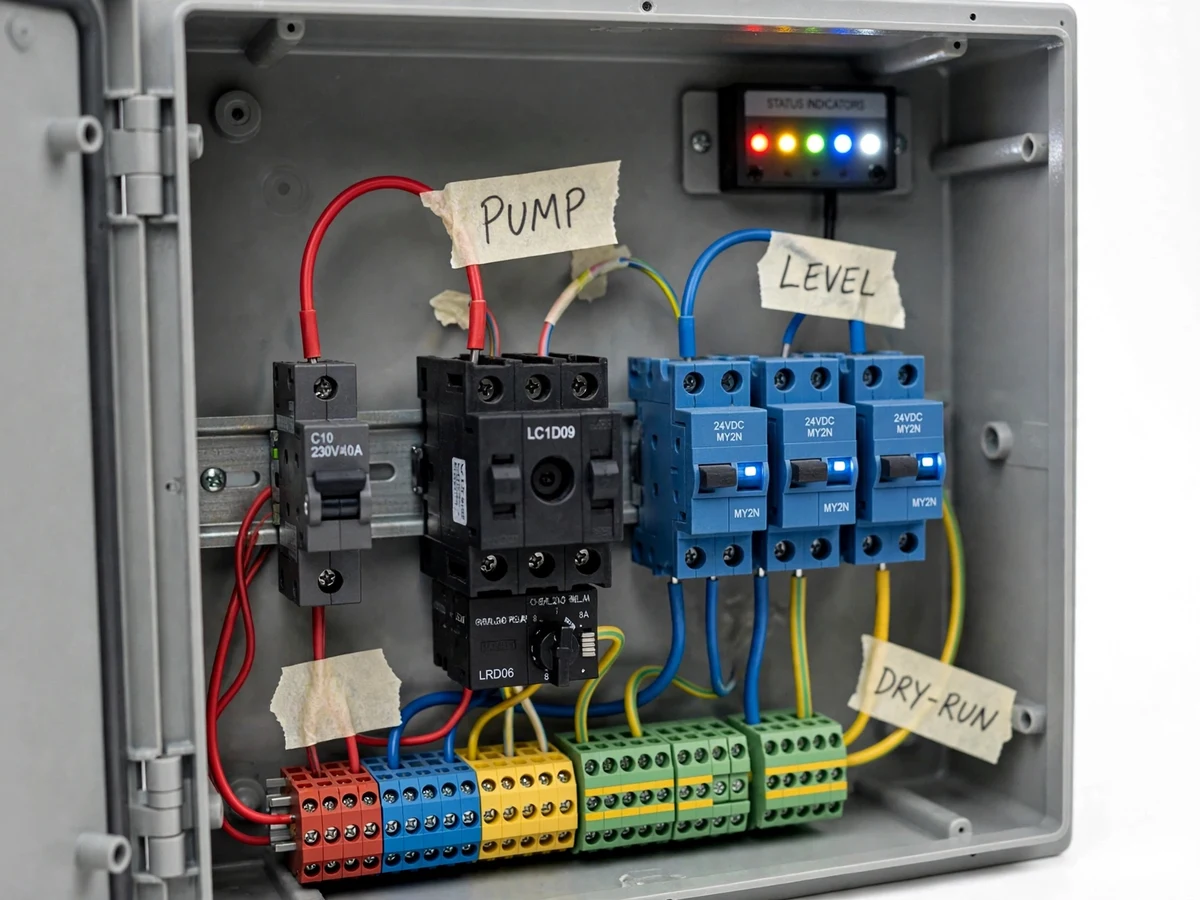
- The same float-switch signals drive the five-LED indicator (Power / Low / Mid / High / Full) on the panel, so the tank state is visible without opening the enclosure.
- The Manual/Auto selector on the panel routes the start command around the level logic for manual running; the overload and dry-run protection remain in circuit in both positions.
Tech stack:
- 3-pole contactor · 12 A AC-3, 230 V AC coil
- Float switches · normally-open level sensors
- Current transformer · dry-run current sensing
- MCB · 10 A Type C supply protection
- Overload relay · adjustable 4–6 A, Class 10
- LED indicator panel · 5-level tank display
- ABS enclosure · IP65, DIN-rail layout
- Manual/Auto selector · panel-mounted switch
| Parameter | Value |
|---|---|
| Supply | 230 V AC ±10%, 50 Hz, single phase (design target) |
| Pump rating supported | Up to 1 HP single-phase submersible (design selection) |
| Contactor | 3-pole, 12 A AC-3 utilization, 230 V AC coil (datasheet) |
| Overload relay | Adjustable 4–6 A, Class 10 (datasheet, set per pump) |
| MCB | 10 A, Type C, 6 kA breaking capacity (datasheet) |
| Float switches | NO contacts, 10 A resistive at 230 V AC (datasheet typical) |
| Dry-run threshold | Below ~70% of set running current for >10 s (design target, adjustable) |
| Level indication | 5 LEDs: Power / Low / Mid / High / Full |
| Enclosure | ABS, IP65 splash-proof (not submersible), approx. 300 × 220 × 120 mm |
| Level response | Level change to contactor action within ~1–2 s (design target) |
| Wiring | 1.5 sq mm control, 2.5 sq mm power, copper (design selection) |
Project features
- [Automatic level control] Two float switches mounted in the overhead tank start the pump when water drops to the low level and stop it at the full level, with seal-in logic so the pump cannot chatter on surface ripples near the switching points. The level logic is wired through control relays that are easy to trace on the ladder-style wiring diagram.
- [Dry-run protection] A current transformer on the motor lead watches the running current: if it stays below the set threshold for longer than the configured delay — the electrical signature of pumping air — the control circuit drops the contactor and latches a dry-run fault. Reset is manual, so the pump cannot silently restart against a dry well.
- [Overload and short-circuit protection] A 10 A Type C MCB on the supply and an adjustable 4–6 A overload relay in the contactor circuit protect the wiring and motor against faults and sustained overloads. Trip ranges are selected for the pump rating and documented in the wiring schedule.
- [LED tank-level indication] A five-LED panel (Power, Low, Mid, High, Full) shows the tank state at a glance from the panel door. The levels are derived from the same float-switch logic that drives the pump, so the display always agrees with the control action.
- [Manual / Auto selector] A panel-mounted selector switch runs the pump manually for testing or maintenance, bypassing the level logic while keeping overload protection active in both positions. This is how the protection functions are demonstrated during evaluation.
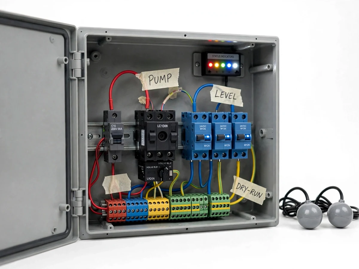
- [Neat control-panel build] All components mount on a DIN rail inside an enclosed ABS panel with labeled terminal blocks, cable glands and an earth busbar. Handwritten masking-tape labels identify every wire bundle — the honest college-prototype style, kept serviceable and explainable.
What is included
- Assembled and wired control panel (contactor, MCB, overload relay, control relays, LED indicator panel)
- Two float switches with approximately 2 m cable each
- Current transformer and dry-run set-point module
- Wiring diagram plus ladder-style control schematic
- Component list with ratings and selection notes
- Installation and commissioning procedure, including the dry-run threshold setting procedure
- Project report PDF (background, design rationale, protection coordination, testing procedure)
- PPT presentation and viva Q&A document
Limitations & prerequisites
- Dry-run detection keys off motor current, which varies with pump model and head — the threshold is set during commissioning with the supplied procedure and is not pre-calibrated for every pump.
- Float switches are mechanical and can foul with scale or debris in hard-water tanks; inspect them every 3–6 months.
- The contactor and overload relay are selected for pumps up to 1 HP single-phase; larger or three-phase pumps need a re-rated starter, available as customization.
- Level switching has ~1–2 s response lag and float hysteresis — this is a controller, not a precision measurement instrument.
- The enclosure is IP65 (splash-proof); it must not be installed where it can be submerged or struck by hose jets.
- Mains wiring must be installed or checked by a competent person; the build includes the wiring diagram and an insulation/continuity test checklist.
- Protection reduces dry-run and overload damage risk but cannot guarantee pump survival — a controller is not a substitute for correct pump selection and plumbing.
Frequently Asked Questions
How does the dry-run protection actually work?
A current transformer watches the pump's running current. If it stays below 70% of the set running value for longer than the configured delay (design target ~10 s) — the signature of pumping air — the control circuit drops the contactor and latches a dry-run fault. Restart needs a manual panel reset, so the pump cannot keep cycling against a dry well. The threshold is set at commissioning.
Does it need a microcontroller or internet?
No. The entire control logic is relay-based: float switches, control relays, contactor and overload relay, with no firmware to crash and no network dependency. That is a deliberate design choice — it makes the panel robust and lets the student trace every wire on the ladder diagram during the viva.
Will it work with my existing pump?
The standard build is designed for single-phase submersible pumps up to 1 HP. If your pump differs, the overload relay range and the dry-run threshold are re-selected during the build. Three-phase or higher ratings are a customization, not part of the base project.
What supply and wiring does it need at site?
A standard 230 V AC single-phase supply. Control wiring is 1.5 sq mm and power wiring 2.5 sq mm copper (design selection). The build ships with the wiring diagram and a continuity/insulation test checklist; mains connections should be made or checked by a competent person.
What maintenance does it need?
Very little: inspect the float switches for scale or debris every 3–6 months, check terminal tightness annually, and re-verify the dry-run threshold if the pump is ever replaced. There is no firmware and no network connection, so there is nothing to update or reconfigure beyond those basic checks.
Is this project suitable for a final-year project?
Yes — for Electrical and related programs. It demonstrates control-circuit design, contactor and relay logic, motor protection (overload, short-circuit, dry-run), panel wiring practice and commissioning — the same discipline behind real motor-control panels, presented at student scale and fully explainable in a viva. Suitable for B.E./B.Tech final-year projects in Electrical Engineering and related branches.
Components & software requirements
- 3-pole contactor · 12 A AC-3, 230 V AC coil
- Float switches · normally-open level sensors
- Current transformer · dry-run current sensing
- MCB · 10 A Type C supply protection
- Overload relay · adjustable 4–6 A, Class 10
- LED indicator panel · 5-level tank display
- ABS enclosure · IP65, DIN-rail layout
- Manual/Auto selector · panel-mounted switch
Delivery information
Built-to-order project. Delivery timeline is shared after order confirmation based on current queue.
Support terms
Complete documentation, setup guide, and viva preparation included. Support for setup and explanation provided.
Download free synopsis (PDF)
Enter your name and email — the synopsis PDF downloads immediately. We may send occasional project updates; no spam, unsubscribe anytime.