
More project photos (3)
The problem
Three-phase induction motors are industry's workhorses — pumps, conveyors, compressors, machine tools — and when one fails, the line stops. Most such failures are not random: sustained overload cooks the winding insulation, a lost phase overloads the remaining two, and overheating degrades the motor long before it seizes. A simple fuse or MCB cannot catch any of this properly — fuses are far too slow for single-phasing and blind to gradual thermal damage. Real factories solve it with protection relays that combine inverse-time overload curves, phase-loss detection and thermal sensing. This project recreates that protection panel at demonstration scale: an ESP32 watches per-phase current through ACS712 sensors, body temperature through a DS18B20 probe and phase presence through optocouplers, then trips a 3-pole contactor within seconds of a fault and logs every trip with its cause — the same protection-coordination thinking, in hardware you can actually demo.
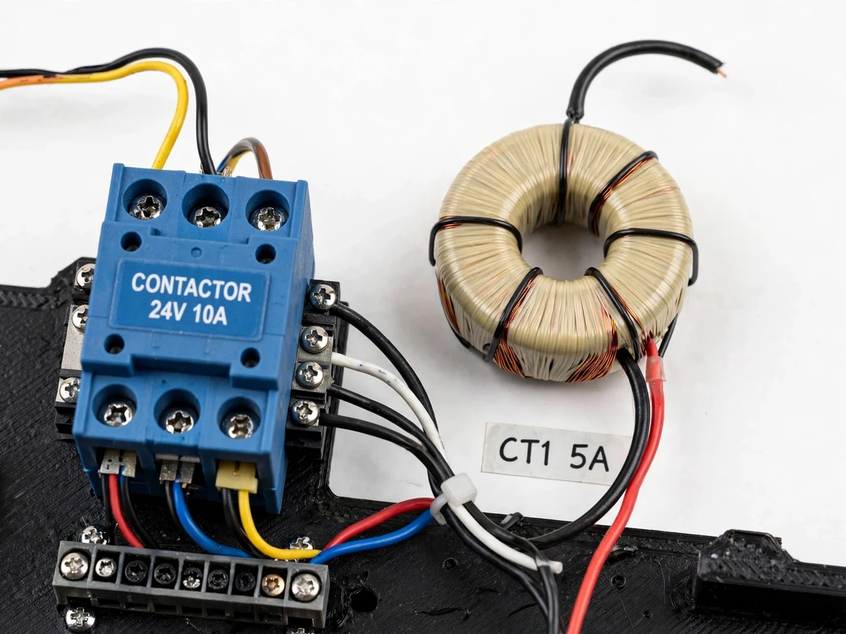
Three ACS712 Hall-effect sensors, one per phase, feeding analog current readings to the ESP32 every mains cycle.
Follow the working sequence
How it works
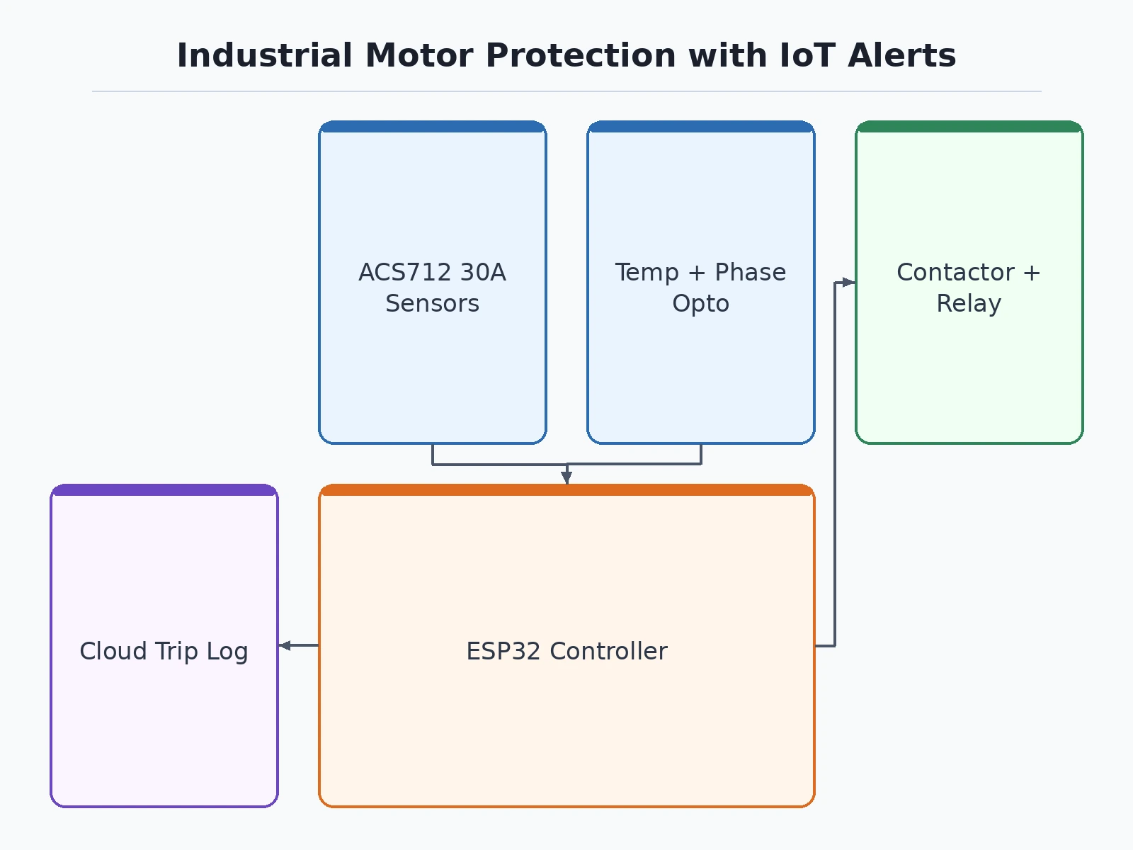
- ACS712 current sensors on each phase feed analog readings to the ESP32, which computes RMS current per phase every mains cycle window.
- Optocoupler circuits monitor each phase's presence; if any phase disappears while the motor is commanded to run, single-phasing is declared.
- The DS18B20 probe tracks motor body temperature against the thermal limit.
- The firmware runs the protection logic: inverse-time accumulation for overload, instantaneous comparison for overcurrent, threshold comparison for temperature, and phase-loss voting.
- On any protection pickup, the ESP32 de-energizes the contactor coil through a relay driver, latches the trip, sounds the buzzer, lights the fault LED and pushes an alert to the dashboard.
- The dashboard logs the trip with its cause and pre-trip readings; the operator investigates, fixes the issue and presses reset to allow restart.
Project features
- Overload protection with an inverse-time (I²t) thermal curve — trips faster on heavier overloads, like a real thermal relay
- Instantaneous overcurrent trip at an adjustable high-set threshold
- Single-phasing / phase-failure detection via optocoupler sensing on each of the three phases
- Motor overheat protection via DS18B20 temperature probe on the motor body
- Automatic contactor trip on any fault — typically removes motor supply within ~2 seconds of fault detection
- Buzzer + fault-specific LED annunciation (overload, overheat, phase loss each get their own indication)
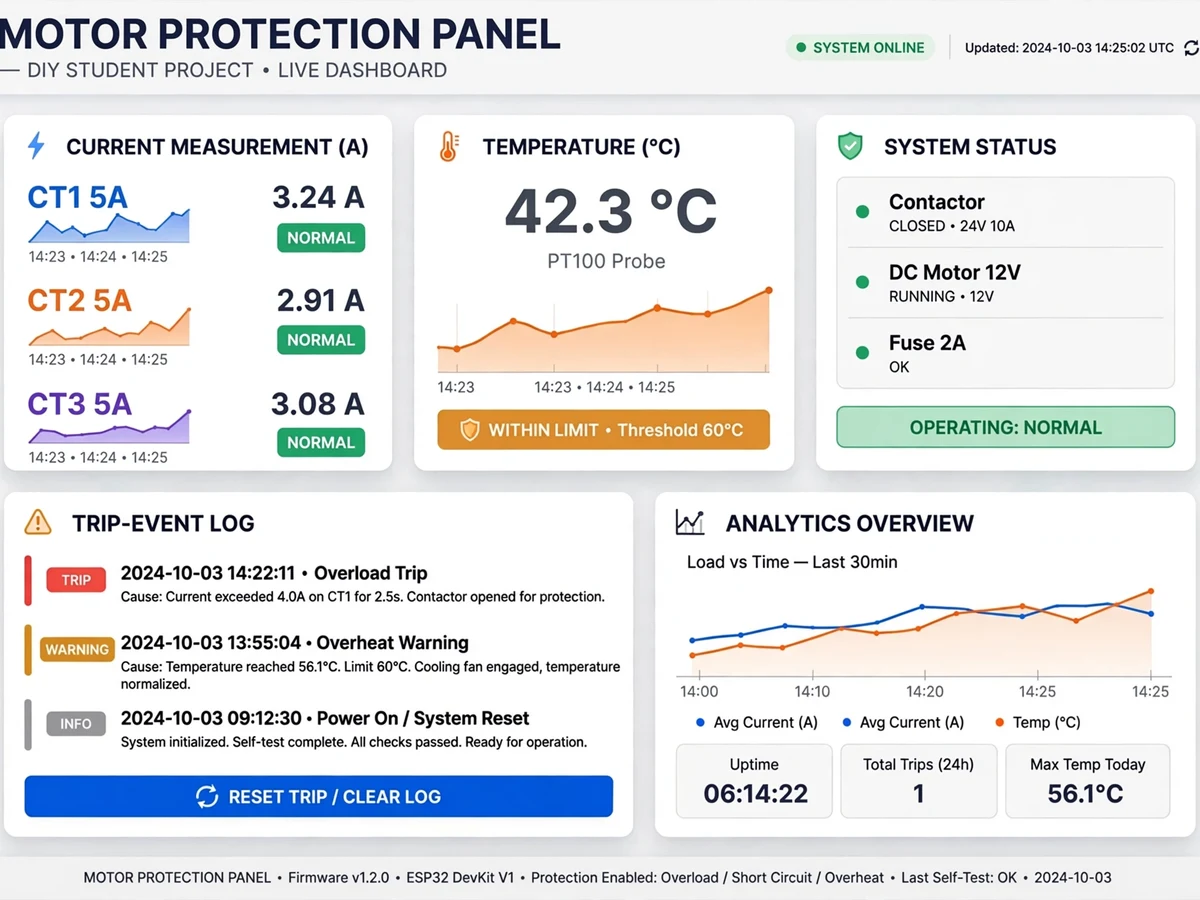
- IoT dashboard with live per-phase current and temperature graphs
- Trip-event log with fault cause, timestamp and pre-trip values for the report
- Manual reset with lockout after a trip — the motor cannot restart until the fault is acknowledged
- Onboard test buttons to simulate overload and phase loss for live demos without real faults
What is included
- Fully assembled motor protection panel with simulated-fault test procedure
- Complete firmware source code (Arduino IDE, well-commented, I²t curve documented)
- Circuit diagram and wiring schematic (power + control + sensing)
- Protection settings and testing procedure sheet
- Project report PDF (protection theory, fault types, simulated-fault test procedure with trip timings, conclusion)
- PPT presentation for final review
- Viva Q&A preparation document (relay curves, single-phasing damage, contactor sizing)
- Dashboard setup guide
FAQs
- Why is motor protection needed — can't a fuse do this? A fuse only responds to gross overcurrent and is far too slow for single-phasing or gradual overheat, which silently destroy motor windings. This panel combines overload (I²t), phase-loss and thermal protection — the three killers of induction motors — and the report explains each with winding-damage diagrams.
- What happens during single-phasing? The optocouplers monitor each phase; when one disappears, the remaining two phases carry ~1.73× current, overheating the windings in minutes. The panel trips the contactor immediately and annunciates "phase loss" — you can demo this by switching off one phase of the demo supply.
- How is the overload trip time calculated? The firmware accumulates I²t (current-squared × time), mimicking a thermal overload relay's heating curve — light overloads take minutes, heavy ones trip in seconds. The settings sheet shows the curve math and how to adjust pickup.
- How do I demo trips safely in my review? The panel has onboard test buttons that simulate overload current and phase loss electronically, so every protection function trips visibly without stressing the demo motor. You see the full sequence: fault → trip → alarm → logged cause.
- Does it need WiFi to protect the motor? No — all protection logic runs locally on the ESP32 and trips the contactor even with WiFi down. The cloud side only adds graphs, alerts and the trip log.
- Can this scale to a real industrial motor? Conceptually, yes — swap the ACS712s for CTs and size the contactor to the motor, and the same protection logic applies. The report covers the scaling math, which makes a strong future-scope slide.
Advantages
- Inverse-time (I²t) thermal curve for overload protection — it trips faster on heavier overloads, mirroring a real thermal overload relay. Automatic contactor trip on any fault — typically removes motor supply within about 2 seconds of fault detection.
- Instantaneous overcurrent trip at an adjustable high-set threshold for short-circuit-level faults.
- Single-phasing and phase-failure detection via optocoupler sensing on each of the three phases.
- Motor overheat protection from a DS18B20 temperature probe mounted on the motor body.
- Fault-specific LED annunciation plus buzzer (overload, overheat, phase loss each get their own indication), a trip-event log with cause, timestamp and pre-trip values, and a manual reset with lockout.
- Onboard test buttons simulate overload and phase loss for live demos without destroying a real motor.
Disadvantages
- Demonstration scale — the prototype protects a small fractional-HP demo motor; industrial motors need appropriately rated contactors and CTs, though the protection logic is identical.
- ACS712 sensors measure up to 30 A; larger motors need external current transformers — the firmware scales to CT ratios.
- Trip timings are validated by simulation (test buttons, injected signals), not by destroying a real motor.
- Cloud alerts need a stable 2.4 GHz WiFi connection; tripping and local annunciation work fully offline.
Limitations & prerequisites
- Demonstration scale — the prototype protects a small demo motor (fractional HP); industrial motors need appropriately rated contactors and CTs, though the protection logic is identical.
- ACS712 sensors measure up to 30 A; larger motors would need external current transformers — the firmware scales to CT ratios.
- Trip timings are validated by simulation (test buttons, injected signals), not by destroying a real motor.
- Cloud alerts need a stable 2.4 GHz WiFi connection; tripping and local annunciation work fully offline.
Components & software requirements
- ESP32 DevKit microcontroller (WiFi, dual-core 240 MHz)
- ACS712 Hall-effect current sensors (30 A rating, one per phase) with RMS computation
- DS18B20 digital temperature probe (motor body overheat sensing)
- Per-phase optocoupler phase-loss detection circuits (4N35-based)
- 3-pole contactor with relay-driver coil switching (motor supply isolation)
- Buzzer + fault-specific LED annunciation panel
- Firmware: Arduino IDE (protection logic, I²t curves, RMS sampling, trip latching)
- IoT dashboard: WiFi → cloud, live current/temperature graphs, trip-event log
Specifications
| Parameter | Value |
|---|---|
| Microcontroller | ESP32 (240 MHz dual-core, WiFi 802.11 b/g/n) |
| Current sensing | ACS712 ×3 (30 A), per-phase RMS computed in firmware |
| Temperature sensing | DS18B20 probe, −55 to +125 °C, ±0.5 °C |
| Phase detection | Optocoupler per phase; single-phasing declared on any phase loss |
| Trip device | 3-pole contactor, relay-driven coil |
| Overload curve | Inverse-time I²t thermal accumulation, adjustable pickup |
| Instantaneous trip | Adjustable high-set overcurrent threshold |
| Trip response | Contactor drop-out typically under ~2 s from fault detection |
| Annunciation | Buzzer + separate LEDs for overload / overheat / phase loss |
| Reset | Manual reset with trip lockout; restart blocked until acknowledged |
| Telemetry | WiFi → dashboard; live graphs + timestamped trip log with causes |
Download free synopsis (PDF)
Enter your name and WhatsApp number — the synopsis PDF downloads immediately. We may send occasional project updates on WhatsApp; no spam.