
More project photos (2)
The problem
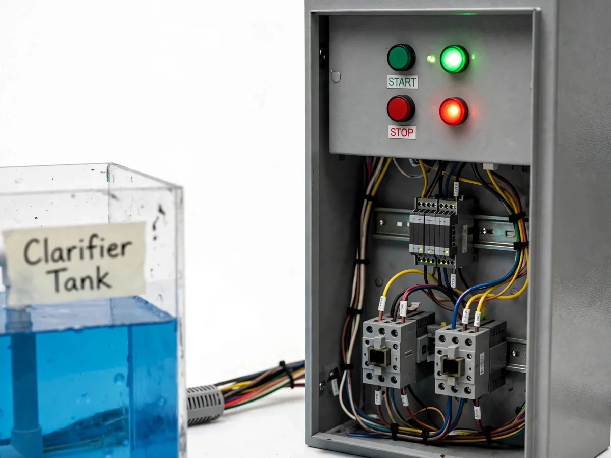
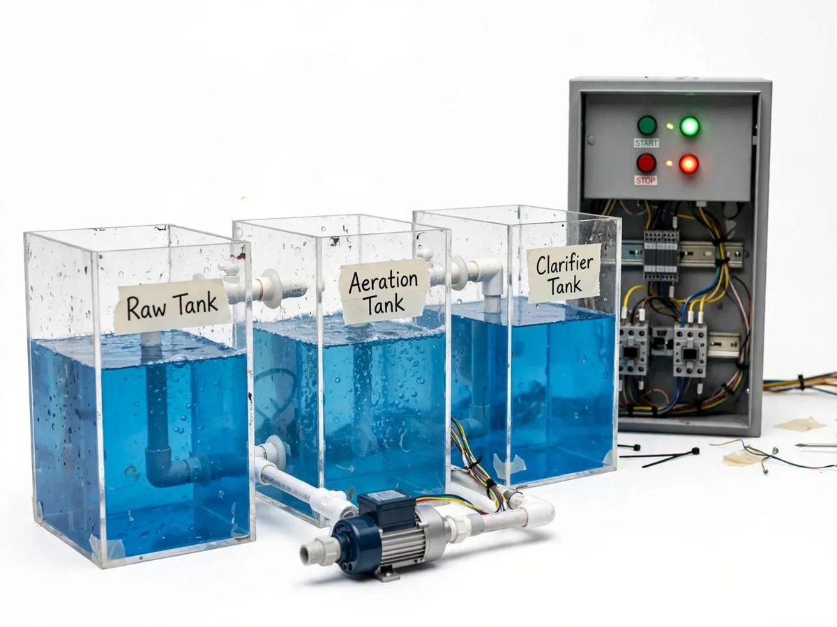
Industrial water treatment plants move raw water through a chain of stages — coagulation, flocculation, sedimentation, filtration and disinfection — and every stage depends on its electrical control: pumps must start and stop in the right order, tanks must not overflow or run dry, and chemical dosing must follow a schedule. Manual operation invites dry running, overflows and inconsistent dosing, which is why real plants are run from PLC-based control panels with motor protection, level interlocks and alarms. Electrical engineering students study these panels in theory but rarely wire and commission one. This project closes that gap with a tabletop working model: transparent stage tanks with real pumps, float switches and a wired control panel demonstrating sequencing, level control, timed dosing and protection.
How it works
- The raw-water pump fills the flocculation tank; its float switch stops the pump at high level and restarts it at low level.
- The dosing pump injects a measured dose on a timer cycle while the agitator motor mixes the tank for a preset time.
- Settled water overflows by gravity into the sedimentation tank model; the transfer pump moves it to the filter bed on level demand.
- The filtered-water pump delivers clear water to the storage tank only when the filter-bed level is healthy, with interlocks preventing dry running.
- A backwash timer periodically reverses the flow path through the filter bed to flush trapped sediment, demonstrating maintenance cycles.
- Any overload trip or overflow condition latches an alarm: the stage lamp turns red and the hooter sounds until the fault is acknowledged and reset.
Tech stack:
- PLC / relay logic: ladder-programmed PLC (Siemens S7-1200 class) or timer-relay panel
- Single-phase pumps for each transfer stage
- Float switches for level sensing
- Contactors, MCB, thermal overload relays
- Push buttons, selector switches, indicator lamps, hooter
- Peristaltic dosing pump with timer
- Transparent acrylic tanks and PVC piping (model hydraulics)
| Parameter | Value |
|---|---|
| Control | PLC (ladder logic) or timer-relay panel — configurable |
| Supply | 230 V AC, single phase, 50 Hz |
| Pumps | 3–4 × single-phase pumps (approx 0.5 HP class) |
| Tanks | 4 transparent stage tanks, approx 10–20 L each |
| Level sensing | Float switches, approx 2 per tank |
| Dosing | Peristaltic pump on adjustable timer cycle |
| Protection | MCB + thermal overload relay per pump circuit |
| Indication | Panel lamps per stage + hooter on trip/overflow |
| Piping | PVC model piping with manual valves |
| Sequencing response | Design target: stage changeover within seconds of level trigger |
Project features
- [Automatic pump sequencing] PLC/timer-relay logic starts the raw-water, transfer and filtered-water pumps in the correct order with interlocks, so a downstream pump cannot start against a dry suction.
- [Float-switch level control] Float switches in each tank hold levels automatically — pumps start on low level and stop on high level without manual intervention.
- [Dosing pump timer control] A peristaltic dosing pump runs on an adjustable timer cycle to demonstrate timed chemical dosing into the flocculation tank.
- [Motor protection wiring] Each pump circuit is wired through an MCB and a thermal overload relay, demonstrating standard industrial motor protection practice.
- [Panel indication and alarms] Indicator lamps show running/stopped/tripped status per stage; a hooter sounds on overload trip or tank overflow.
- [Manual / auto selector] A selector switch per stage lets the operator run the model in manual mode for demonstration or automatic mode for unattended sequencing.
- [Backwash cycle demonstration] A timed valve-and-pump sequence reverses flow through the filter bed model to demonstrate filter backwashing.
What is included
- Working tabletop treatment-plant control model with wired panel
- PLC ladder program (or relay wiring schedule) source files
- Panel wiring diagram and component layout drawing
- Complete component list with ratings
- Project report PDF (background, control logic, protection, testing procedure)
- PPT presentation for final review
- Viva Q&A preparation document (PLC logic, motor protection, level control)
- Setup and demonstration guide
Limitations & prerequisites
- Demonstration model at tabletop scale — piping, flows and timings are illustrative, not sized to a real plant.
- Water is recirculated for demonstration; the model does not produce potable water and is not a certified treatment device.
- Pump duty is light; running the model dry or continuously for long hours can overheat the pumps.
- Float-switch positions need careful setting during commissioning — the setup guide covers this.
- Timer-based dosing approximates chemical dosing; real plants use flow-paced dosing with analyzers.
Frequently Asked Questions
Which controller is used?
A ladder-programmed PLC (Siemens S7-1200 class) runs the sequencing logic; a timer-relay panel version can be built instead where a PLC is not required by the college. The wiring diagram and program ship with the project.
Does it actually treat water?
It demonstrates the treatment stages and their electrical control — pumping, mixing, timed dosing, filtration and backwash sequencing. It is a control-system model, not a certified water-treatment device.
What power supply is needed?
A standard 230 V AC single-phase socket; the panel steps control circuits down to 24 V DC where used. No three-phase supply is needed for the model.
Can the stages be changed?
Yes — tank count, pump order and timer values are configurable in the PLC program or timer settings, so the model can be adapted to a college-specified process flow.
What are the main limitations?
Tabletop scale, recirculated demonstration water, light-duty pumps, and float switches that need careful commissioning — the full list is in Limitations & Prerequisites.
Is this project suitable for a final-year project?
Yes — for Electrical Engineering programs. It demonstrates PLC ladder logic, motor protection, level-control sequencing and panel wiring, all strong viva material. Suitable for B.E./B.Tech final-year projects in Electrical Engineering.
Components & software requirements
- PLC / relay logic: ladder-programmed PLC (Siemens S7-1200 class) or timer-relay panel
- Single-phase pumps for each transfer stage
- Float switches for level sensing
- Contactors, MCB, thermal overload relays
- Push buttons, selector switches, indicator lamps, hooter
- Peristaltic dosing pump with timer
- Transparent acrylic tanks and PVC piping (model hydraulics)
Delivery information
Built-to-order project. Delivery timeline is shared after order confirmation based on current queue.
Support terms
Complete documentation, setup guide, and viva preparation included. Support for setup and explanation provided.