
More project photos (3)
The problem
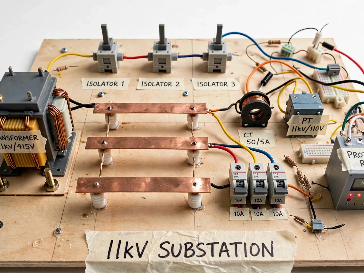
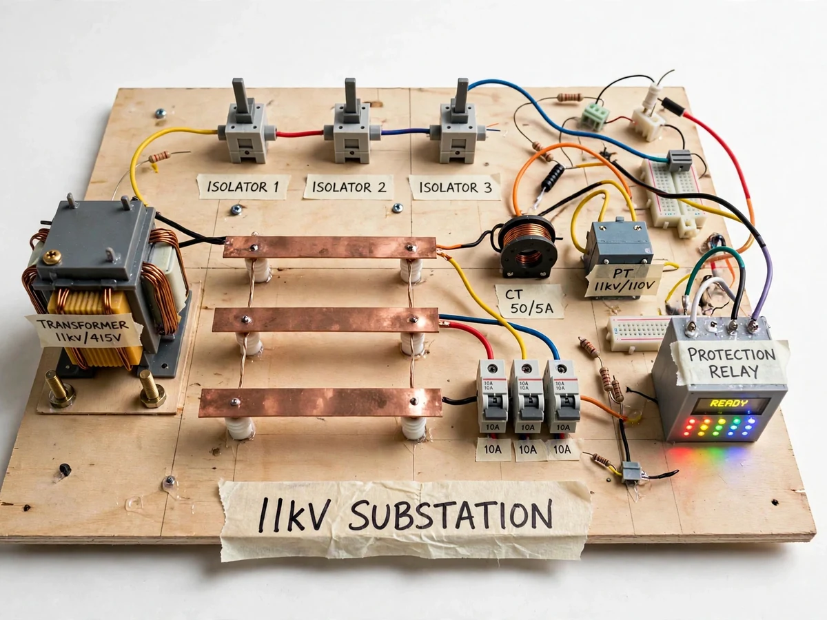
Substation layouts are taught through single-line diagrams that students learn to draw long before they understand what each symbol is in physical space. This project closes that gap with a tabletop model of an 11 kV distribution substation. A miniature 11 kV/415 V transformer feeds copper bus-bars mounted on insulator posts; isolator switches, a CT (50/5 A) and PT (11 kV/110 V) models, miniature circuit breakers and a protection relay box with LED status indicators complete the yard. Every component carries a masking-tape label, so the student can walk an examiner through the complete power flow: incoming, bus, metering, protection, outgoing. The model turns the single-line diagram into a physical place.
Miniature 11 kV/415 V transformer that anchors the yard and represents the incoming supply.
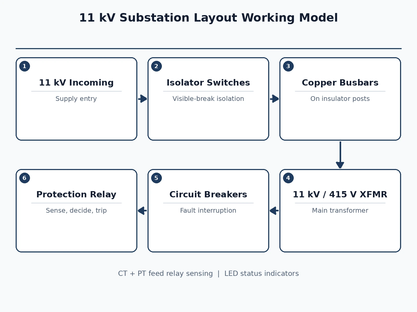
Follow the working sequence
How it works
- The miniature transformer represents the incoming 11 kV supply stepped to the distribution voltage.
- Power flows through the isolator switches onto the three copper bus-bars mounted on insulator posts.
- The CT and PT models tap the bus for the metering and protection signal path, demonstrated by the labeled wiring to the relay box.
- The miniature circuit breakers sit in the outgoing feeders, representing the fault-interrupting devices.
- The protection relay box shows status on its LEDs; the demonstration guide walks through a trip-and-isolate switching sequence on the model.
- The student presents the complete flow against the single-line diagram, pointing at each physical component.
Tech stack:
- Miniature 11 kV/415 V transformer model
- Copper bus-bars on insulator posts
- Miniature isolator switches (x3)
- CT model (50/5 A) and PT model (11 kV/110 V)
- Miniature circuit breakers
- Protection relay demonstration box
- Wooden base board with layout
- Single-line diagram and demo guide
| Parameter | Value |
|---|---|
| Layout | 11 kV distribution substation, tabletop model scale (design target) |
| Transformer | Miniature, labeled 11 kV/415 V (model, not a real rating) |
| Bus-bars | 3 x copper bars on insulator posts |
| Isolators | 3 x miniature switches |
| Instrument transformers | CT 50/5 A model, PT 11 kV/110 V model (labels, not real ratios) |
| Breakers | Miniature models, labeled 10 A class |
| Relay box | LED status indicators with READY display (demonstration) |
| Demo | Switching-sequence guide, buyer-run |
Project features
- [Miniature power transformer] A model 11 kV/415 V transformer anchors the yard, labeled with its ratio, representing the substation's main transformation.
- [Copper bus-bar section] Three copper bus-bars on insulator posts form the bus, the physical heart of the substation layout the single-line diagram abstracts away.
- [Isolator switches] Three miniature isolator switches demonstrate the visible-break isolation used before maintenance.
- [CT and PT models] A 50/5 A current transformer model and an 11 kV/110 V potential transformer model show where metering and protection derive their signals.
- [Circuit breakers] Miniature breakers represent the fault-interrupting devices, labeled with their ratings.
- [Protection relay box] A relay box with LED status indicators and a READY display demonstrates the protection concept: sense, decide, trip.
- [Buyer-run demonstration guide] A documented guide for the switching sequence demo: energize, isolate, and the safe switching order, plus the single-line diagram of the model.
- [Complete viva kit] Report covering substation equipment, layouts and protection, plus PPT and viva Q&A.
What is included
- Miniature substation transformer model
- Copper bus-bar assembly with insulators
- Three isolator switches
- CT and PT models
- Miniature circuit breakers
- Protection relay demonstration box
- Base board with complete layout and labels
- Single-line diagram of the model
- Switching demonstration guide
- Project report PDF (substation equipment, layouts, protection concepts)
- PPT presentation for final review
- Viva Q&A preparation document
Limitations & prerequisites
- This is a demonstration model at tabletop scale; it carries no real 11 kV and must never be presented as switchgear or connected to mains.
- All ratings on the models (11 kV/415 V, CT 50/5 A, PT 11 kV/110 V) are representative labels for teaching, not measured or certified ratings.
- The protection relay box demonstrates the protection concept with LEDs; it does not perform real fault detection or tripping.
- The switching sequence is a demonstration procedure, not an operating procedure for real substations.
- Fault levels, clearances and earthing of a real yard are described in theory only.
Frequently Asked Questions
What equipment does the model include?
A miniature transformer, three bus-bars on insulators, three isolators, CT and PT models, miniature breakers and a protection relay box — the standard equipment set of a distribution substation, each labeled.
Is any part of this model live at 11 kV?
No — nothing in the model carries high voltage. It is a teaching model, and the documentation states this safety boundary explicitly.
What is the difference between an isolator and a breaker?
The isolator gives a visible break for maintenance isolation and cannot break load current; the breaker interrupts fault current. The model shows both side by side, and the report explains the distinction.
What do the CT and PT do?
They step down current and voltage to safe, measurable levels for meters and protection relays — the models show exactly where they sit in the layout.
How is the model demonstrated?
The guide walks through energizing the yard, reading the relay status LEDs, and performing the isolate-and-maintain switching sequence in the correct order.
Is this project suitable for a final-year project?
Yes — for Electrical engineering programs. Substation layout and switchgear are core power-systems topics, and a physical model the student can walk an examiner through is an excellent demo. Suitable for B.E./B.Tech final-year projects in Electrical engineering.
Components & software requirements
- Miniature 11 kV/415 V transformer model
- Copper bus-bars on insulator posts
- Miniature isolator switches (x3)
- CT model (50/5 A) and PT model (11 kV/110 V)
- Miniature circuit breakers
- Protection relay demonstration box
- Wooden base board with layout
- Single-line diagram and demo guide
Delivery information
Built-to-order project. Delivery timeline is shared after order confirmation based on current queue.
Support terms
Complete documentation, setup guide, and viva preparation included. Support for setup and explanation provided.
Download free synopsis (PDF)
Enter your name and WhatsApp number — the synopsis PDF downloads immediately. We may send occasional project updates on WhatsApp; no spam.