
More project photos (2)
The problem
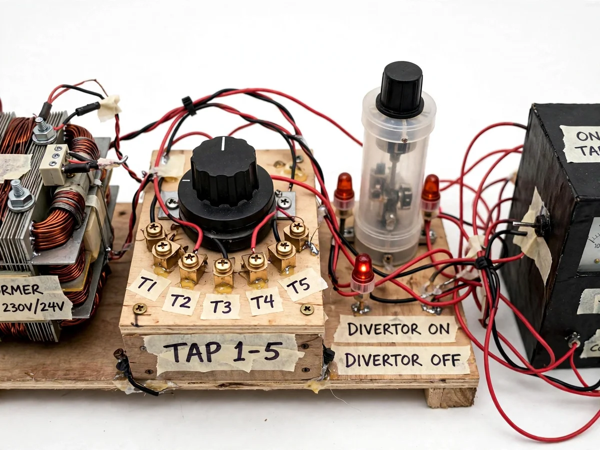
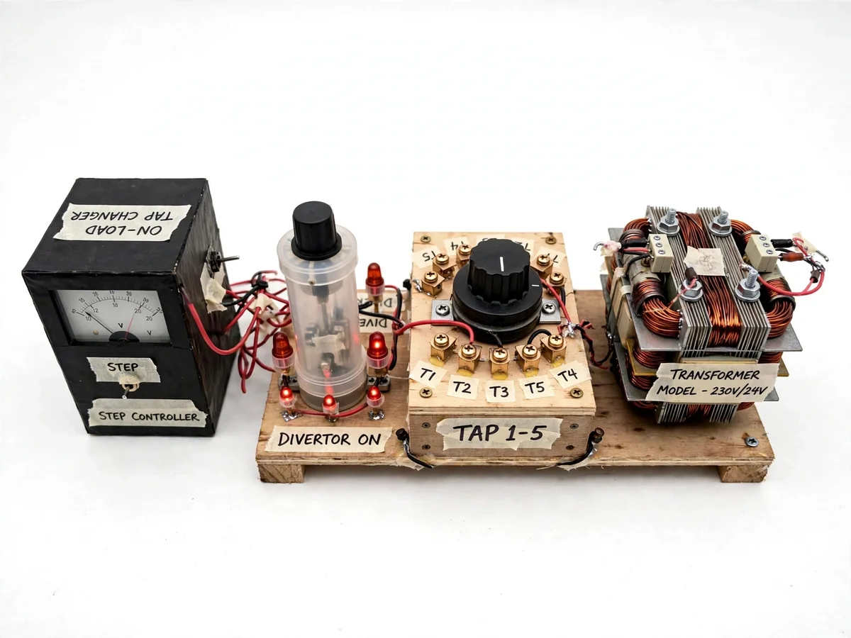
Distribution voltage must stay within limits as load changes through the day; the classic way to hold it is changing the transformer's turns ratio — its tap position. Off-circuit tap changers move only with the transformer dead — an outage every time voltage needs correction. On-load tap changers solve this by moving taps while the transformer stays energized and loaded, and the trick that makes it possible is the diverter switch: it hands the load current from one tap to the next through transition resistors, so the winding section between taps is never shorted and current is never interrupted. This project builds that mechanism as a working model. A small single-phase transformer is wound with five accessible taps; a rotary selector with moving contacts pre-selects the next tap; a diverter chamber with transition resistors performs the transfer; a voltmeter on the secondary shows each voltage step; and a lamp load bank keeps it loaded so every tap change happens genuinely on-load. The hand-operated, exposed selector-diverter sequence lets the student perform the exact steps a real OLTC executes automatically.
How it works
- The transformer is energized from the mains through an isolation transformer, and the lamp load bank is switched on so the secondary carries load current.
- The tap position lamp shows the current tap, and the voltmeter reads the corresponding secondary voltage.
- To raise the voltage, the rotary selector is turned to pre-select the next higher tap — the selector moves with no load current flowing through it.
- The diverter lever is then operated: it bridges the two taps through the transition resistors, so load current momentarily flows through the resistor path.
- The diverter completes its travel, handing the full load current to the new tap and taking the old tap and resistors out of circuit — the make-before-break transfer.
- The voltmeter shows the stepped-up voltage and the tap lamp updates; the sequence is repeated to step through all five taps, then reversed to step down.
- The selector interlock is demonstrated by attempting to move the selector mid-transfer, which the interlock blocks.
Tech stack:
- On-load tap changing theory
- Tap selector and diverter design
- Transition resistor bridging
- Small power transformer construction
- Selector drive mechanism
- AC voltmeter instrumentation
- Interlock logic
- Lamp load bank
| Parameter | Value |
|---|---|
| Transformer model | Single-phase, 230 V / 24 V, approximately 200 VA (design) |
| Taps | 5 positions on secondary (design) |
| Step voltage | Approximately 2.5% per tap (design target) |
| Diverter | Manual lever with transition resistors (design) |
| Load bank | Lamp load, approximately 50 W (design) |
| Supply | 230 V AC mains via isolation transformer (design) |
| Selector | Manual rotary with position lamps (design) |
| Tap indication | Panel lamps, one per position (design) |
Project features
- [Five-tap transformer model] A small single-phase transformer wound with five accessible secondary taps gives a real voltage step at each position.
- [Rotary tap selector] A hand-operated rotary selector with moving contacts pre-selects the next tap while carrying no load current, exactly as in a real OLTC.
- [Diverter switch with transition resistors] The exposed diverter chamber transfers load current between taps through transition resistors, demonstrating the bridging sequence that prevents tap-to-tap shorts.
- [On-load demonstration] A lamp load bank keeps the transformer loaded during every change, so the voltage step is observed under genuine on-load conditions.
- [Step voltmeter] A panel voltmeter on the secondary shows the voltage rise or fall at each tap change, making regulation visible.
- [Selector-diverter interlock] A mechanical interlock prevents the selector from moving while the diverter is mid-transfer, enforcing the correct operating sequence.
- [Tap position indication] Lamps on the panel show the active tap at all times, so the audience follows each change.
What is included
- Small transformer with five accessible secondary taps
- Rotary tap selector and diverter switch assembly with transition resistors
- Control panel with voltmeter, tap lamps and interlock
- Lamp load bank
- Wiring and schematic diagram of selector-diverter connections
- Project report PDF (background, OLTC theory, diverter sequence, readings)
- PPT presentation for final review
- Viva Q&A preparation document (selector vs diverter, transition resistors, tap steps)
Limitations & prerequisites
- The model works at low voltage (24 V secondary); real OLTCs operate at high voltage with completely different insulation and clearances.
- The diverter switches small currents — arc interruption phenomena of real diverters are simplified, not replicated.
- There is no vacuum or oil diverter chamber; the transfer is visible in air by design, for teaching.
- The manual selector moves far slower than a real motor-driven diverter, which completes transfer in milliseconds.
- Five taps demonstrate the principle; real units commonly have 17 or more positions.
- This is a teaching model, not grid equipment — it is not rated for any real distribution duty.
Frequently Asked Questions
Why change taps under load at all?
Because system voltage drifts with load, and an off-circuit tap change needs the transformer de-energized — an outage. The OLTC corrects voltage continuously while supply stays on, which is what distribution networks actually need.
What is the diverter switch?
The switch that actually carries the load current during a tap change. While the selector pre-selects the next tap at no load, the diverter moves under load, bridging the two taps through transition resistors so current is never interrupted.
Why are transition resistors needed?
During the transfer the diverter briefly connects two adjacent taps. Without the resistors that would short the winding section between the taps, driving a huge circulating current. The resistors limit that current while the bridge exists.
What happens if the diverter is operated wrongly?
That is exactly what the interlock prevents. Wrong sequencing can short taps or interrupt load current; the model includes a mechanical interlock so only the correct selector-then-diverter order is possible.
How is this different from an off-circuit tap changer?
An off-circuit changer is a simple selector moved only when the transformer is dead. The OLTC adds the diverter, transition resistors and sequencing so taps move under full load — the model demonstrates precisely this difference.
Is this project suitable for a final-year project?
Yes — for Electrical Engineering programs. It makes the diverter-selector sequence of on-load tap changing visible and operable, which is the heart of the topic. Suitable for B.E./B.Tech final-year projects in Electrical Engineering.
Components & software requirements
- On-load tap changing theory
- Tap selector and diverter design
- Transition resistor bridging
- Small power transformer construction
- Selector drive mechanism
- AC voltmeter instrumentation
- Interlock logic
- Lamp load bank
Delivery information
Built-to-order project. Delivery timeline is shared after order confirmation based on current queue.
Support terms
Complete documentation, setup guide, and viva preparation included. Support for setup and explanation provided.