
More project photos (3)
The problem
Inductive loads — motors, transformers, welding sets — draw lagging reactive power that drags down bus voltage and loads distribution lines with current that does no useful work. Utilities and large plants traditionally correct this with switched capacitor banks, but those switch in coarse steps, cannot absorb excess reactive power, and wear out their contactors. A STATCOM (static synchronous compensator) answers with power electronics: a voltage-source converter connected in shunt that synthesizes a controllable AC voltage and exchanges continuously variable reactive power with the network, supporting voltage and correcting power factor with no moving parts. This project builds a laboratory-scale STATCOM model around a three-phase two-level IGBT voltage-source converter. A DC-link capacitor bank, a coupling reactor and an STM32 controller running a grid-synchronized d-q current loop connect the converter to a scaled, isolated AC bus. The demonstration shows reactive-power injection and absorption on demand, bus-voltage support under a switching inductive load, and the d-q control theory behind every modern FACTS device — all measurable live on the display and an oscilloscope.
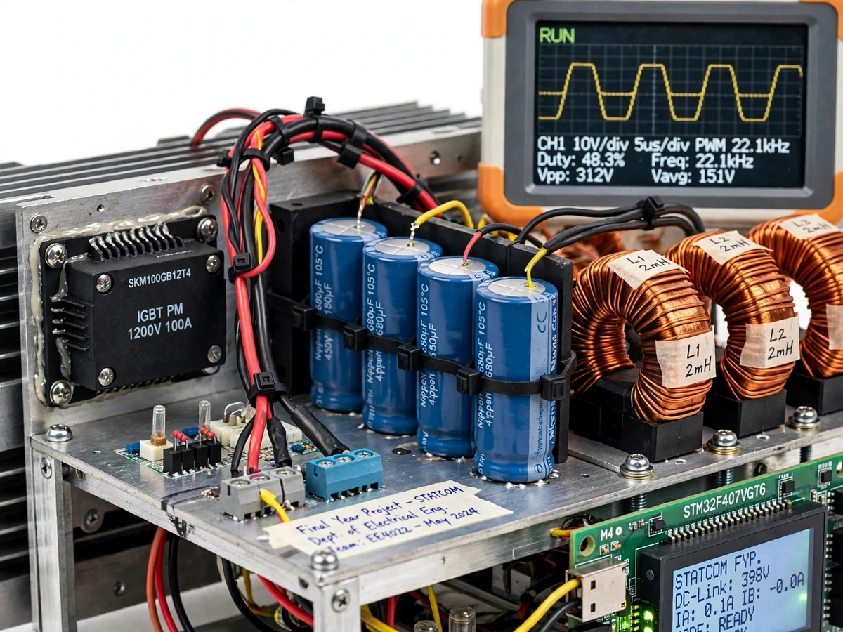
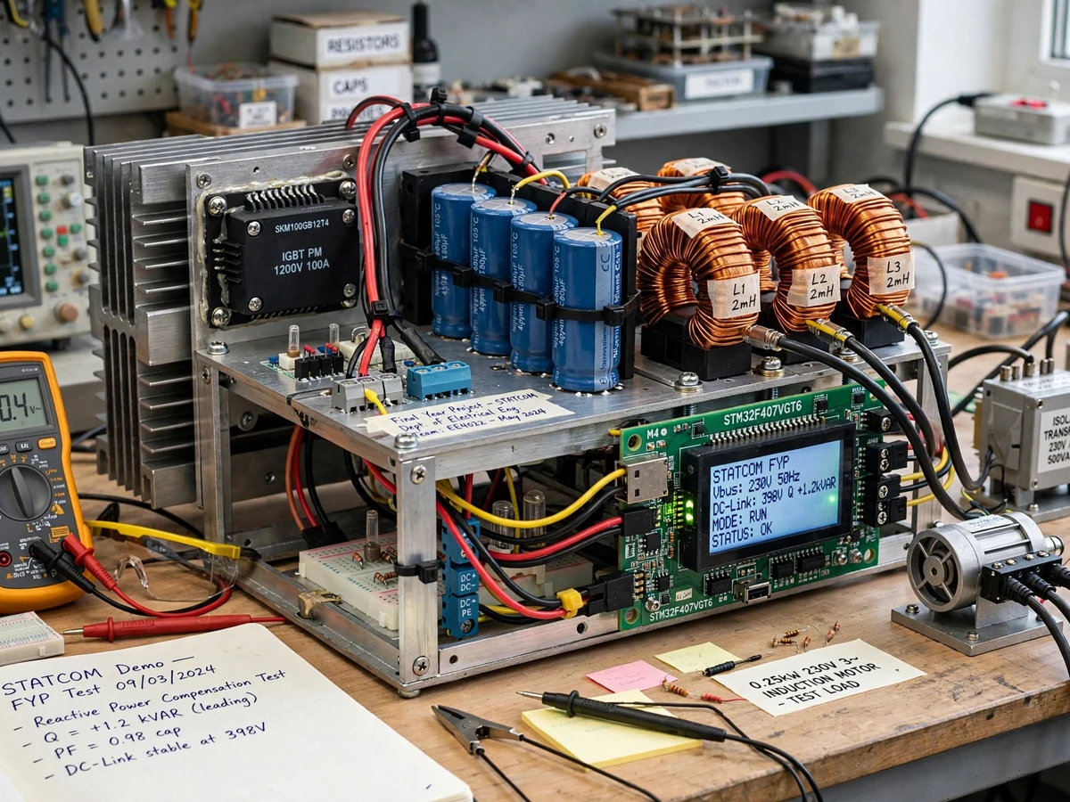
Scaled three-phase bus via an isolation transformer, feeding the test load.
Follow the working sequence
How it works
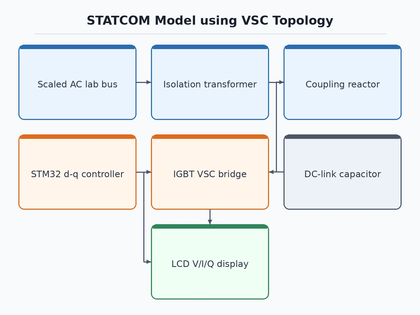
- A scaled three-phase lab bus (via an isolation transformer) feeds the test load and the STATCOM's coupling reactor; the VSC bridge connects to the bus through the reactor.
- At power-up the precharge path charges the DC-link capacitor bank through a resistor, then the contactor bypasses the resistor and the controller enables the gate drivers.
- Hall-effect transducers sample bus voltage and converter current; the PLL extracts the bus angle and the controller transforms the currents into the d-q frame.
- The operator's reactive-power reference is compared with measured Q; the q-axis PI controller — plus the d-axis DC-link regulator — produce voltage references in the rotating frame.
- An inverse transform plus sine-triangle PWM turns those references into gate pulses for the six IGBTs at the configured switching frequency.
- The synthesized converter voltage, placed slightly above or below the bus voltage in phase, drives a controlled reactive current through the coupling reactor — injecting or absorbing VArs.
- The display updates bus voltage, current, Q and power factor continuously; switching the inductive test load in and out shows the STATCOM holding the bus voltage steady.
Tech stack:
- STM32F4-class microcontroller (PLL, d-q transforms, PI loops, PWM generation)
- Three-phase IGBT intelligent power module with integrated gate drivers
- DC-link electrolytic capacitor bank with precharge resistor and contactor
- Three-phase coupling reactor (line inductors)
- Hall-effect voltage and current transducers (isolated sensing)
- Isolation transformer providing the scaled lab AC bus
- LCD for live V, I, Q and power-factor readout
- STM32CubeIDE firmware; oscilloscope and power analyzer for verification
| Parameter | Value |
|---|---|
| Topology | Three-phase two-level VSC, sine-triangle PWM |
| Lab bus | Scaled AC via isolation transformer; design 110 V L-L |
| DC-link voltage | Design target ~200 V DC (set from bus voltage; soft-precharged) |
| Reactive power range | Design target ±500 VAr at scaled bus (coupling-reactor and thermal dependent) |
| Switching frequency | 5–10 kHz configurable (thermal- and filter-dependent) |
| Control | STM32: PLL + d-q PI current control with DC-link voltage loop |
| Sensing | Hall-effect V and I transducers, galvanically isolated |
| Operating modes | Manual Q setpoint; automatic bus-voltage regulation (configurable) |
| Protection | Precharge, overcurrent, DC overvoltage, overtemperature trips |
Project features
- [Three-phase VSC power stage] A six-switch IGBT bridge (intelligent power module) with a DC-link electrolytic capacitor bank forms the voltage-source converter. The bridge synthesizes a controllable three-phase AC voltage from the DC link — the heart of every STATCOM.
- [d-q current control loop] A PLL locks to the lab-bus angle and transforms measured currents into the rotating reference frame, so reactive current is regulated independently of active current with two PI controllers — the standard industrial control structure.
- [Reactive-power setpoint control] The operator dials in a reactive-power reference — inject or absorb — and the controller tracks it, demonstrating leading/lagging compensation and power-factor correction on the live display.
- [DC-link voltage regulation] A slow outer loop draws a small active current to hold the DC-link capacitor at its setpoint against switching and conduction losses, keeping the converter self-sustaining without an external DC source.
- [Automatic voltage-support mode] As a configurable mode, the STATCOM regulates the bus voltage itself: it injects reactive power when the bus sags under a switching load and absorbs it when the bus rises.
- [Soft precharge and fault protection] A precharge resistor and contactor limit DC-link inrush at power-up; overcurrent, DC overvoltage and heatsink-overtemperature trips shut the gates down with a latched fault LED.
- [Live electrical readout] An LCD shows bus voltage, converter current, reactive power and power factor in real time, giving examiners verifiable numbers during the demonstration.
What is included
- Assembled VSC power stage on chassis (IGBT module, DC-link bank, precharge, heatsink)
- STM32 control board with firmware (PLL, d-q control, protection, display)
- Coupling reactor set and scaled-bus isolation transformer arrangement
- Circuit schematic and wiring diagram
- Bill of materials with part numbers and sourcing notes
- Project report PDF (VSC theory, d-q control design, buyer-run test procedure)
- PPT presentation for final review
- Viva Q&A preparation document (STATCOM, VSC, d-q control, reactive power)
- Setup and demo guide (safe power-up sequence, demonstrating Q injection/absorption)
Advantages
- The six-switch IGBT bridge with DC-link capacitor bank forms a real three-phase voltage-source converter that synthesizes a controllable AC voltage.
- PLL-based d-q current control with two PI controllers regulates reactive current independently of active current, the standard industrial control structure.
- The operator can dial in a reactive-power reference to inject or absorb, demonstrating leading and lagging compensation and power-factor correction on the live display.
- A slow outer loop holds the DC-link voltage against switching and conduction losses, keeping the converter self-sustaining without an external DC source.
- Automatic voltage-support mode injects reactive power when the bus sags under a switching load and absorbs it when the bus rises.
Disadvantages
- This is an academic lab model at scaled voltage, not a grid-connected device, and it must never be tied to the utility mains; all testing needs qualified supervision with the isolation transformer in place.
- The reactive-power range and DC-link figures are design targets derived from the scaled bus voltage and component ratings, not type-tested values.
- Real network phenomena such as harmonics, unbalance and grid faults are represented only by the lab bus and test load, so the model demonstrates control principles, not utility-grade performance.
- Sustained full-range operation needs the specified heatsink and airflow, confirmed by the buyer's thermal check, since switching losses set the continuous operating envelope.
- This is an educational prototype with no grid-code compliance, EMC certification or utility approval.
Limitations & prerequisites
- Academic lab model at scaled voltage, not a grid-connected device: it must never be tied to the utility mains, and all testing needs qualified supervision with the isolation transformer in place.
- The ±500 VAr range and DC-link figures are design targets derived from the scaled bus voltage and component ratings, not type-tested values; the report includes a buyer-run measurement procedure with an oscilloscope/power analyzer.
- Real network phenomena — harmonics from nonlinear loads, unbalance, grid faults — are represented only by the lab bus and test load; the model demonstrates control principles, not utility-grade performance.
- Switching losses and heatsink sizing set the continuous operating envelope; sustained full-range operation needs the specified heatsink and airflow, confirmed by the buyer's thermal check.
- Control tuning (PI gains, PLL bandwidth) is configuration-dependent; the firmware ships with defaults verified on the reference build, and retuning guidance is included.
- This is an educational prototype with no grid-code compliance, EMC certification or utility approval.
Frequently Asked Questions
Is this project suitable for a final-year project?
Yes — for Electrical Engineering and power-systems programs. It demonstrates FACTS concepts, VSC operation, d-q control, PLL synchronization and reactive-power theory with live, measurable results — strong viva material.
What does the STATCOM actually do in the demo?
It injects or absorbs reactive power on a scaled lab bus: switch an inductive load in and the bus voltage sags; the STATCOM injects VArs and restores it. The display shows Q and power factor changing in real time.
Which controller and power devices are used?
An STM32F4-class microcontroller runs the PLL, d-q transforms and PI loops; the power stage is a three-phase IGBT intelligent power module with a DC-link capacitor bank and coupling reactor.
Can it connect to the real mains?
No. This is a scaled laboratory model fed through an isolation transformer, strictly for supervised lab demonstration. It has no grid-code compliance or utility approval.
Is the ±500 VAr rating measured?
It is a design target derived from the scaled bus voltage and component ratings. The report includes a buyer-run test procedure so you measure the actual reactive-power range on your own build.
What will I receive with the project?
The assembled VSC power stage, STM32 controller with firmware, coupling reactor and transformer arrangement, schematics, BOM, project report PDF, PPT, viva Q&A and a setup/demo guide. Suitable for B.E./B.Tech final-year projects in Electrical Engineering and power systems.
Components & software requirements
- STM32F4-class microcontroller (PLL, d-q transforms, PI loops, PWM generation)
- Three-phase IGBT intelligent power module with integrated gate drivers
- DC-link electrolytic capacitor bank with precharge resistor and contactor
- Three-phase coupling reactor (line inductors)
- Hall-effect voltage and current transducers (isolated sensing)
- Isolation transformer providing the scaled lab AC bus
- LCD for live V, I, Q and power-factor readout
- STM32CubeIDE firmware; oscilloscope and power analyzer for verification
Delivery information
Built-to-order project. Delivery timeline is shared after order confirmation based on current queue.
Support terms
Complete documentation, setup guide, and viva preparation included. Support for setup and explanation provided.
Download free synopsis (PDF)
Enter your name and WhatsApp number — the synopsis PDF downloads immediately. We may send occasional project updates on WhatsApp; no spam.