
More project photos (2)
The problem
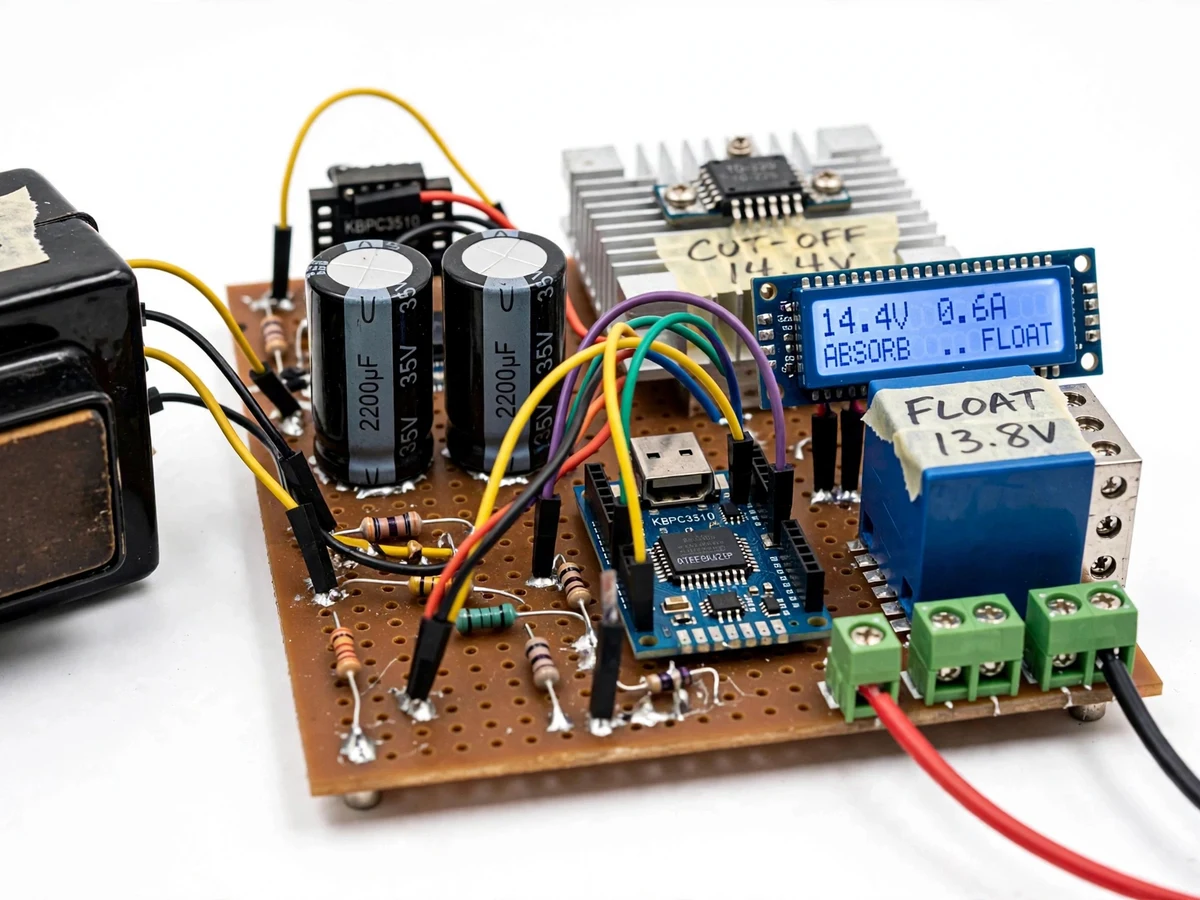
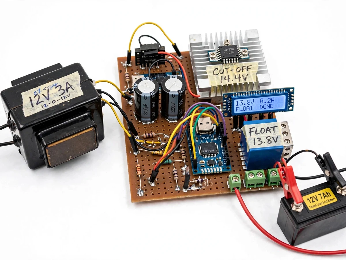
Most small chargers sold to students are single-stage trickle chargers or raw unregulated adapters. A trickle charger left on too long overcharges the battery — gassing, water loss and warped plates. A dumb adapter undercharges it — and chronic undercharging is what sulfates plates and silently kills batteries that would otherwise last years. Proper charging needs three distinct stages: bulk to refill fast at constant current, absorption to hold ~14.4 V until the battery is genuinely full, and float at ~13.8 V to compensate self-discharge without cooking the cells. This project is a working mains-powered charger that does exactly that on an Arduino Nano controller. A 12-0-12 V centre-tapped transformer, bridge rectifier and filter bank produce the raw DC; the controller reads battery voltage and charge current, drives a pass MOSFET through the three stages, and opens a cut-off relay when absorption is complete. The design includes reverse-polarity protection and an over-temperature cut-out on the heatsink — the kind of protection thinking examiners probe in the viva. Everything is built openly: transformer, rectifier, regulator, sensing, relay logic and firmware, so the student can explain each block and its numbers.
12-0-12 V centre-tapped 3 A transformer steps mains down for the charger.
Follow the working sequence
How it works
- 230 V AC steps down through the 12-0-12 V centre-tapped transformer (3 A rated); both secondaries feed the KBPC bridge rectifier and the 2×2200 µF / 35 V filter capacitors, producing unregulated DC.
- The Arduino Nano reads battery voltage through a resistor divider and charge current through a low-side sense resistor roughly every 200 ms.
- BULK stage: while the battery is below ~14.4 V, the firmware holds the pass MOSFET on at the current-limited set-point (~1.5–2 A design target) for fast charging.
- ABSORB stage: at ~14.4 V the controller holds voltage constant; when the charge current tapers below the ~0.25 A design target, the battery is declared full and the cut-off relay opens.
- FLOAT stage: after cut-off, the controller maintains the battery at ~13.8 V through the maintenance path, compensating self-discharge without overcharging.
- The 16×2 LCD refreshes every second with voltage, current and stage; the reverse-polarity fuse and heatsink thermistor guard the power stage throughout.
Tech stack:
- Arduino Nano (ATmega328P)
- 12-0-12 V, 3 A centre-tapped transformer
- KBPC bridge rectifier · 2×2200 µF filter bank
- IRFZ44N N-MOSFET pass device on aluminium heatsink
- Resistor-divider voltage sense · low-side current sense
- 16×2 character LCD (I2C backpack)
- 12 V, 10 A cut-off relay
- Embedded C++ (Arduino framework)
| Parameter | Value |
|---|---|
| Input mains | 230 V AC, 50 Hz (design target operating range 210–250 V) |
| Transformer | 12-0-12 V, 3 A, centre-tapped (manufacturer rating) |
| Rectifier | KBPC3510, 35 A / 1000 V max (datasheet) |
| Battery type | 12 V sealed lead-acid, 4–14 Ah recommended (design target) |
| Bulk charge current | 1.5–2 A, constant current (firmware set-point, design target) |
| Absorption voltage | 14.4 V hold, cut-off on current taper below ~0.25 A (design targets) |
| Float voltage | 13.6–13.8 V (design target) |
| Cut-off relay | 12 V coil, 10 A contacts (datasheet) |
| Display | 16×2 character LCD: voltage, current, stage (component spec) |
| Over-temperature cut-out | Heatsink thermistor, ~75 °C trip (design target) |
Project features
- [Three-stage charging state machine] Bulk (constant current), absorption (constant voltage ~14.4 V design target with current-taper detection), float (~13.8 V design target) — implemented in Arduino firmware with documented transition thresholds.
- [Auto cut-off relay] A 10 A relay disconnects the battery from the charging path when the absorption criteria are met; the controller re-engages charging if the battery voltage sags below the reconnect threshold.
- [Live voltage & current display] 16×2 LCD shows measured battery voltage, charge current and the active stage (BULK / ABSORB / FLOAT), updated every second.
- [Transformer-isolated power stage] 12-0-12 V, 3 A centre-tapped transformer (manufacturer rating) feeding a KBPC-series bridge rectifier and a 2×2200 µF / 35 V filter bank.
- [Current-limited bulk output] Charging current is limited by the current-sense resistor and firmware set-point, design target ~1.5–2 A, suitable for 4–14 Ah sealed lead-acid batteries.
- [Reverse-polarity protection] Series fuse plus polarity-guard relay wiring so a reversed battery cannot drive current back into the controller or the power stage.
- [Over-temperature cut-out] Thermistor on the pass-transistor heatsink pauses charging above the design limit (~75 °C design target) until the heatsink cools.
- [Documented calibration procedure] Step-by-step charge-cycle procedure using a multimeter and a discharged battery, run during your calibration to trim the firmware set-points.
What is included
- Working charger prototype (transformer, controller board, cut-off relay, LCD, battery leads)
- Arduino firmware source with the documented three-stage state machine and trimmable set-points
- Circuit schematic and wiring diagram (PDF)
- Charge-cycle calibration procedure (multimeter + discharged battery steps)
- Project report PDF (background, rectifier/regulator theory, methodology, design targets)
- PPT presentation for final review
- Viva Q&A preparation document (rectification, three-stage charging, sensing, relay logic, protection)
Limitations & prerequisites
- 12 V lead-acid only (flooded, AGM or gel) — NOT for Li-ion, LiFePO4 or 24 V systems; those need different voltage profiles and chemistries.
- All stage voltages and the 1.5–2 A current limit are design targets set during the build; no charge curve was measured on this exact unit before delivery — the buyer runs the documented calibration procedure with their own battery.
- Efficiency is a design estimate (~75–80% for the transformer stage), not a measured claim.
- Large automotive batteries (>40 Ah) would charge extremely slowly; this design targets 4–14 Ah packs — a bigger transformer is a different design.
- The firmware does not attempt recovery of batteries below ~9 V terminal voltage; deeply sulfated batteries need bench recovery first.
- The 230 V mains side must be used with the isolating enclosure and fuse as documented; it is not touch-safe when open.
Frequently Asked Questions
Why three stages instead of a fixed charging voltage?
Because a battery is not a resistor. Bulk at constant current refills fast; absorption holds ~14.4 V until the current tapers so the battery is genuinely full; float at ~13.8 V only compensates self-discharge. A single fixed voltage either undercharges (sulfation) or overcharges (gassing, water loss).
How does the auto cut-off actually work?
During absorption the controller holds ~14.4 V and watches the charge current. When it tapers below the ~0.25 A design threshold, the firmware declares the battery full and opens the cut-off relay. If the battery later sags below the reconnect threshold, charging restarts.
Can it charge my car battery?
Physically it connects and charges, but a car battery is 35–45 Ah and this design targets 4–14 Ah — it would take very long. Bigger batteries need a bigger transformer and a revised current set-point.
What happens if I connect the battery backwards?
The series fuse and polarity-guard relay wiring prevent any reverse current from reaching the controller or the power stage — the fault shows up as zero current on the LCD.
Can I trim the voltage set-points?
Yes — every threshold (absorption voltage, cut-off current, float voltage, reconnect point) is a named constant at the top of the firmware, and the delivery includes a calibration procedure using a multimeter and a discharged battery.
Is this project suitable for a final-year project?
Yes — for Electrical and Electronics programs. It covers mains power supplies, rectification and filtering, voltage regulation, current sensing, embedded state-machine design and protection engineering, all in one demonstrable build. Suitable for B.E./B.Tech final-year projects in Electrical, Electronics and IoT.
Components & software requirements
- Arduino Nano (ATmega328P)
- 12-0-12 V, 3 A centre-tapped transformer
- KBPC bridge rectifier · 2×2200 µF filter bank
- IRFZ44N N-MOSFET pass device on aluminium heatsink
- Resistor-divider voltage sense · low-side current sense
- 16×2 character LCD (I2C backpack)
- 12 V, 10 A cut-off relay
- Embedded C++ (Arduino framework)
Delivery information
Built-to-order project. Delivery timeline is shared after order confirmation based on current queue.
Support terms
Complete documentation, setup guide, and viva preparation included. Support for setup and explanation provided.
Download free synopsis (PDF)
Enter your name and email — the synopsis PDF downloads immediately. We may send occasional project updates; no spam, unsubscribe anytime.