
More project photos (2)
The problem
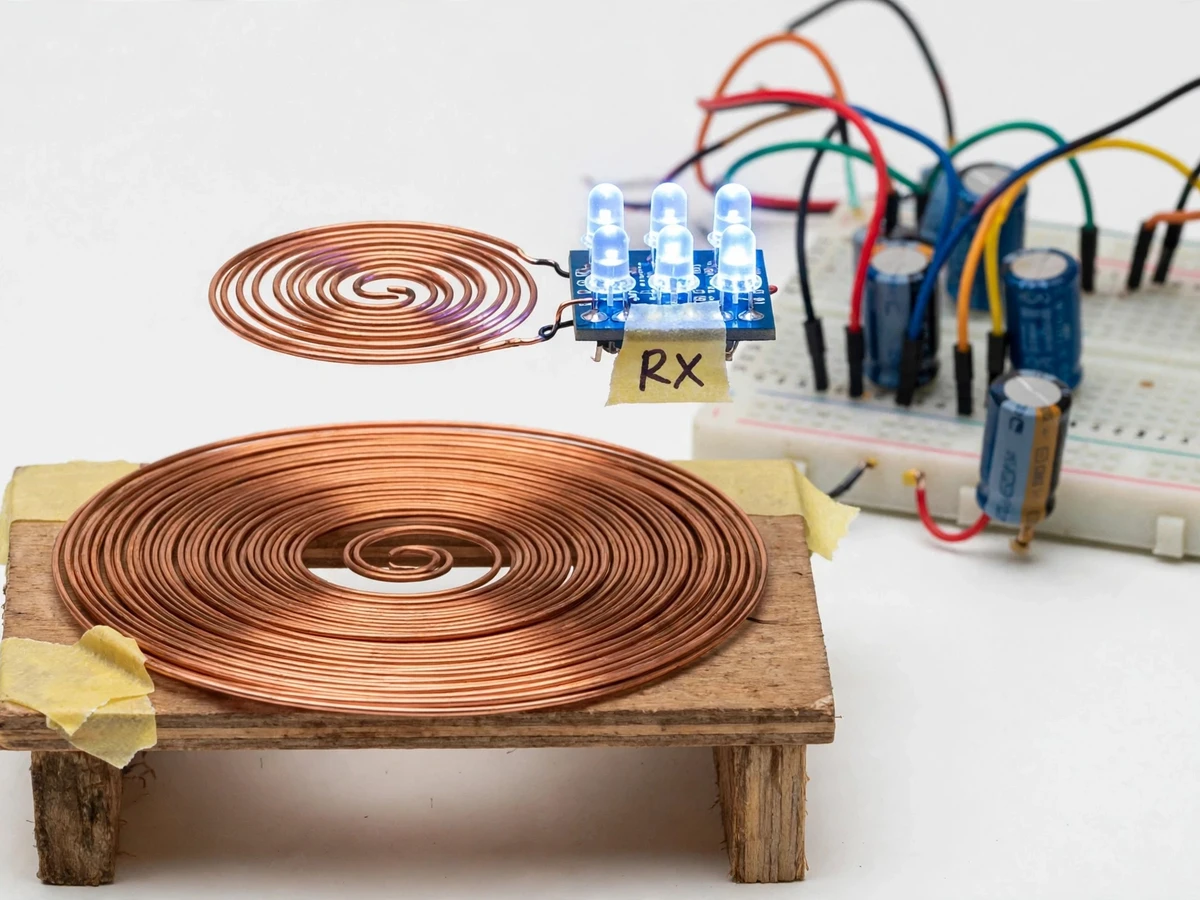
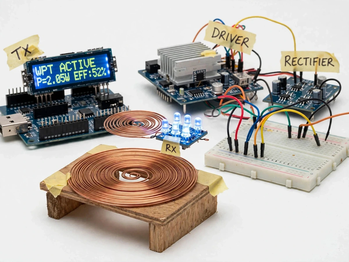
Wireless charging pads and EV charging prototypes all rely on inductive power transfer, yet students usually meet the idea only as a formula — f = 1/(2π√LC) — with no sense of how sharply a detuned coil collapses the output. This kit makes the physics tangible: two hand-wound spiral coils, each paired with a resonant capacitor, face each other across a small air gap while a NE555-driven MOSFET oscillator excites the transmitter at the resonant frequency. The receiver rectifies the induced AC and powers an LED array or a small fan, and an Arduino with an INA219 monitor and a 16x2 LCD shows input voltage and current, receiver output power and the computed transfer efficiency in real time. A structured tuning procedure has the student calculate the resonant frequency from the measured coil inductance, select the tuning capacitance, and fine-tune until the LEDs peak — then map efficiency against coil separation and misalignment. That is the point of the build: resonance theory verified by the student's own measurements, in a working demo powered from a 12 V DC adapter.
Wired as an astable oscillator at the resonant frequency, about 73.4 kHz, driving a MOSFET.
Follow the working sequence
How it works
- The NE555 is wired as an astable oscillator at the computed resonant frequency (approximately 73.4 kHz for the 100 µH / 47 nF design values) and drives a logic-level MOSFET.
- The MOSFET switches the transmitter tank — spiral coil plus series resonant capacitor — at resonance, building a strong alternating magnetic field across the air gap.
- The receiver spiral coil, tuned with its own series capacitor to the same frequency, captures the field; operating both tanks at resonance amplifies the induced voltage on the receiver side.
- A Schottky bridge rectifier and filter capacitor convert the receiver AC into DC, which powers the LED array, small fan or resistive load.
- The INA219 sensor measures the transmitter supply voltage and current, and the Arduino multiplies them to obtain true input power.
- A resistor divider feeds the receiver DC voltage into the Arduino ADC; firmware divides the square of that voltage by the known load resistance to get output power, then displays efficiency (Pout ÷ Pin) on the 16x2 LCD.
- The student runs the tuning procedure: measure the coil inductance, compute f = 1/(2π√LC), select the tuning capacitance, fine-tune the trimmers while watching LED brightness and the efficiency readout, then record efficiency versus separation distance for the report graphs.
Tech stack:
- Arduino Uno (ATmega328P)
- NE555 timer + logic-level MOSFET driver
- INA219 I2C power monitor
- 16x2 character LCD
- Hand-wound spiral TX/RX coils
- Schottky bridge rectifier + filter stage
- Arduino IDE (C/C++ firmware)
- 12 V DC adapter supply
| Parameter | Value |
|---|---|
| Controller | Arduino Uno (ATmega328P) |
| Oscillator / driver | NE555 astable + logic-level MOSFET (design) |
| Current and voltage sensing | INA219: 12-bit ADC, 0–26 V bus range, I2C interface (datasheet) |
| Display | 16 × 2 character LCD |
| Transmitter coil inductance | Approximately 100 µH (design value; the student measures their own coil) |
| Resonant capacitance | Approximately 47 nF (design value; trimmers and selectable capacitors for tuning) |
| Resonant frequency | Approximately 73.4 kHz (calculated from design values via f = 1/(2π√LC)) |
| Transmitter supply | 12 V DC adapter (design) |
| Input power | Approximately 2–10 W (design target range) |
| Demo air gap | Approximately 1–6 cm (design target operational range) |
| Receiver output | Approximately 3–6 V DC at close alignment (design target) |
| Transfer efficiency | Design target up to 60% at ~1 cm alignment — not a measured claim; a 30–50% range is typical of careful student builds (expected, varies with coil winding and alignment) |
| Loads | LED array, 5 V DC fan, resistive dummy load |
Project features
- [Resonant transmitter tank] The transmitter is a hand-wound spiral copper coil paired with a series resonant capacitor; design values of 100 µH and 47 nF put the tank at approximately 73.4 kHz, computed from f = 1/(2π√LC).
- [NE555 oscillator driver stage] A NE555 timer wired as an astable oscillator drives a logic-level MOSFET that switches the transmitter tank at the resonant frequency; the ~73 kHz target sits comfortably inside the NE555's practical astable range, so the oscillator runs with stable timing and honest component margin.
- [Resonant receiver with rectifier] The receiver spiral coil is tuned with its own series capacitor to the same frequency, and a Schottky bridge rectifier with filter capacitor converts the induced AC into DC for the LED array or small fan load.
- [INA219 input power sensing] A TI INA219 module (12-bit ADC, 0–26 V bus range, I2C — datasheet values) measures the transmitter supply voltage and current so the Arduino can compute true input power.
- [Live efficiency display on LCD] The 16x2 LCD continuously shows input voltage and current, receiver output power, and transfer efficiency (output power ÷ input power) as a percentage, updated live.
- [Hands-on resonance tuning] Selectable tuning capacitors and trimmer adjustment let the student deliberately detune and re-tune both tanks, watching the LEDs and the efficiency readout peak at resonance.
- [Interchangeable DC loads] An LED array, a small 5 V DC fan and a resistive dummy load are included, so the output-power measurement procedure can be repeated against a known load resistance.
- [Efficiency-vs-distance experiment procedure] A documented procedure has the student record efficiency at increasing coil separations and misalignments, producing the graphs that carry the report and viva.
What is included
- Working wireless power transfer prototype (coils, driver, rectifier, Arduino + LCD, loads)
- Arduino firmware: input/output power computation and LCD efficiency display
- Coil winding and resonant-tuning procedure document
- Circuit diagram and wiring documentation
- Component list with part roles
- Efficiency-vs-distance measurement procedure with graph template
- Project report PDF (background, resonance theory, methodology, student-measured results)
- PPT presentation for final review
- Viva Q&A preparation document (resonance, coupling, rectification, measurement method)
Limitations & prerequisites
- Efficiency figures are design targets, not measured claims — every number in the report comes from the student's own measurement run.
- Both coils must be tuned to the same resonant frequency; a detuned tank visibly collapses the output, which is the experiment's point, not a fault.
- Transfer falls off quickly with distance and misalignment: the demo range is a few centimetres, and metal objects near the coils disturb the field.
- The MOSFET and driver stage dissipate heat at higher input power; the build targets the 2–10 W design range with a heatsink, not kilowatt transfer.
- This is a demo kit with LED/fan loads — it is not Qi/WPC certified and cannot charge commercial phones or devices.
- The 12 V DC adapter keeps everything low-voltage, but the transmitter tank rings at high AC voltage internally; the board is not to be probed while powered.
Frequently Asked Questions
Which controller and measurement parts are used?
An Arduino Uno (ATmega328P) runs the firmware that computes the power figures. A TI INA219 module measures the transmitter supply voltage and current over I2C, giving true input power. A 16x2 character LCD continuously shows input voltage and current, receiver output power and the computed transfer efficiency as a percentage, so the entire measurement chain is visible during the demo.
What is the operating frequency and how is it set?
The build targets the LC resonance f = 1/(2π√LC), which works out to approximately 73.4 kHz for the 100 µH coil and 47 nF capacitor design values. The student measures their own hand-wound coil's inductance, selects the tuning capacitance by calculation, and then fine-tunes trimmers while watching the LEDs and the efficiency readout peak — so the frequency is found by measurement, not assumed.
Can it charge a phone or follow the Qi standard?
No. This is a teaching demonstration with LED and fan loads; it implements neither Qi/WPC negotiation nor certification. That boundary is stated plainly on the page and in the report — the project demonstrates resonant inductive transfer and efficiency measurement, and it must not be presented as a charger for commercial devices.
What power supply is needed and is it safe to handle?
A 12 V DC adapter, specified in the component list, powers everything — there is no mains wiring in the build. Keep metal objects away from the coils while it is running, since they disturb the field and can heat up, and do not probe the transmitter tank while powered because it rings at high AC voltage internally.
Can the driver be upgraded to a ZVS driver?
Yes, as an optional customization. A ZVS (Mazzilli) driver stage can be supplied in place of the NE555 stage for higher drive efficiency at the same resonant frequency. The base project ships with the NE555-driven stage documented on the page, so any ZVS variant is quoted and built separately rather than assumed.
Is this project suitable for a final-year project?
Yes — for Electronics, E&TC and Electrical programs. It demonstrates LC resonance, inductive coupling, power-electronics switching, rectification and genuine power measurement in one build. The measurement-driven report, with the student's own tuning data and efficiency-versus-distance graphs, gives direct material for viva questions on resonance, coupling and instrumentation.
Components & software requirements
- Arduino Uno (ATmega328P)
- NE555 timer + logic-level MOSFET driver
- INA219 I2C power monitor
- 16x2 character LCD
- Hand-wound spiral TX/RX coils
- Schottky bridge rectifier + filter stage
- Arduino IDE (C/C++ firmware)
- 12 V DC adapter supply
Delivery information
Built-to-order project. Delivery timeline is shared after order confirmation based on current queue.
Support terms
Complete documentation, setup guide, and viva preparation included. Support for setup and explanation provided.
Download free synopsis (PDF)
Enter your name and email — the synopsis PDF downloads immediately. We may send occasional project updates; no spam, unsubscribe anytime.