
More project photos (3)
The problem
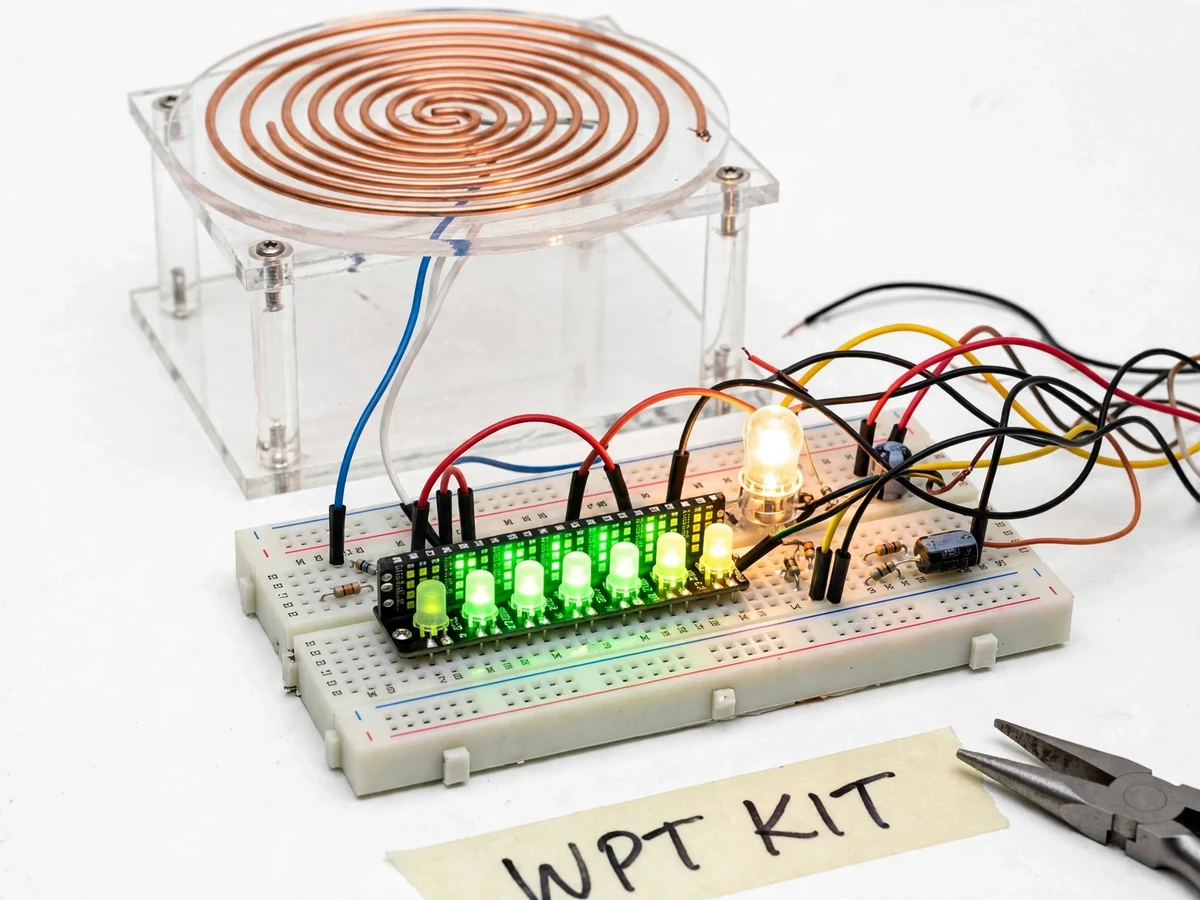
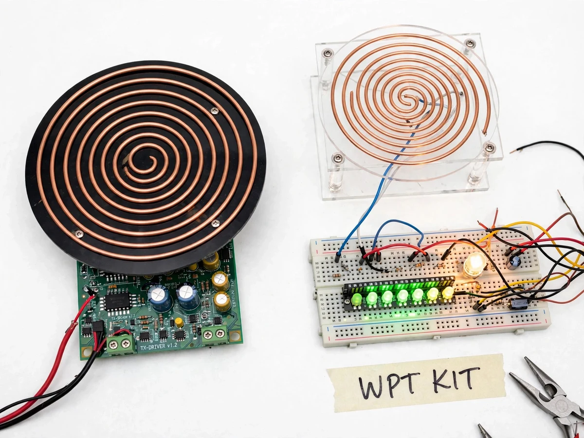
Wireless power transfer looks simple in theory — two coils, one magnetic field — but the physics hides in resonance and alignment, and most student builds stop at "the LED lit up" without explaining why it lit. A receiver coil that glows at 1 cm and goes dark at 6 cm is a better teacher than any equation, and this kit makes that lesson direct and measurable. Its distinguishing instrument is a 10-LED bar-graph indicator wired to the rectified receiver voltage, so every change in distance, angle or alignment registers instantly on a live coupling meter. Around it sits a complete resonant inductive link: a ZVS-style high-frequency driver board, hand-wound enamelled-copper transmitter and receiver coils tuned with capacitors to resonance, and an LED demo load. The build is documented as a measurement exercise — winding the coils, tuning to resonance, calibrating the indicator, then recording bar-graph level against distance and misalignment to plot the efficiency-vs-distance curve that anchors the report.
Regulated 12 V bench supply powering the driver board.
Follow the working sequence
How it works
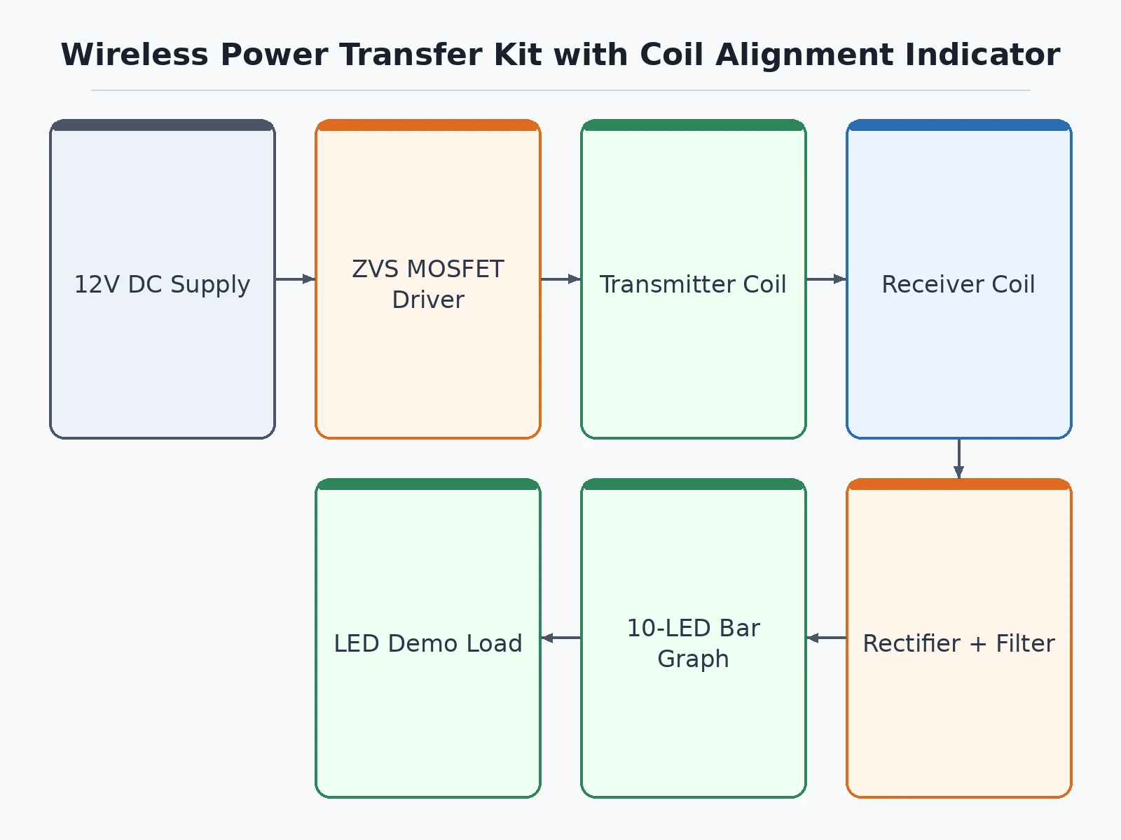
- A 12 V DC supply powers the ZVS-style driver board, which switches the transmitter coil at its resonant frequency (approximately 100–200 kHz, design target).
- The coil's alternating magnetic field threads the receiver coil across the air gap, inducing an AC voltage by mutual induction.
- Series capacitors tune both coils near resonance, so the link peaks at the driver frequency — detuning collapses transfer, which the student verifies deliberately.
- On the receiver side, a bridge rectifier and filter convert the captured AC to DC for the LED load and the charging-demo output.
- A tap of the rectified receiver voltage feeds the LM3914-style bar-graph driver, lighting 0–10 LEDs in proportion to coupling strength.
- Sliding the receiver coil sideways or lifting it drops the lit bars in real time; the student records bar level at fixed positions to build the efficiency-vs-distance curve.
- During assembly, resonant capacitors are selected and the indicator's full-scale point is calibrated with the buyer's own multimeter, following the included procedure.
Tech stack:
- ZVS-style resonant driver board (MOSFET switching stage)
- Hand-wound enamelled copper coils (28 SWG, design values)
- LM3914-style 10-LED bar-graph indicator
- Bridge rectifier + filter (receiver DC stage)
- 12 V DC regulated bench supply
- Acrylic coil mounts + solderless breadboard assembly
- Multimeter · oscilloscope (tuning and calibration)
- Resonance math: LC tuning and coupling coefficient (report)
| Parameter | Value |
|---|---|
| Input supply | 12 V DC regulated (datasheet value) |
| Driver frequency | Approximately 100–200 kHz (design target, ZVS-style stage) |
| Transmitter coil | Approximately 60 turns, 28 SWG enamelled copper, 8 cm diameter (design value) |
| Receiver coil | Approximately 35 turns, 28 SWG enamelled copper, 6 cm diameter (design value) |
| Usable transfer distance | Up to approximately 8 cm (expected; output becomes negligible beyond) |
| End-to-end efficiency | Approximately 20–30% at close coupling (design target, falls rapidly with distance) |
| Alignment indicator | 10-LED bar graph, 0–10 scale driven by rectified receiver voltage |
| Demo load | LED lamp; 5 V charging-demo output, approximately 1 W maximum (design target) |
| EMI guidance | Keep at least 30 cm from sensitive receivers during demos (design guidance) |
| Coil mounts | Acrylic disc mounts on perforated base |
Project features
- [LED bar-graph alignment indicator] The project's distinguishing feature: a 10-LED bar graph (LM3914-style driver) fed by the rectified receiver voltage, showing coupling strength live on a 0–10 scale. Every alignment change registers instantly.
- [Resonant inductive coupling] Transmitter and receiver coils are hand-wound from enamelled copper wire and tuned with capacitors to the driver's resonant frequency, so transfer peaks sharply at resonance — exactly the viva's favorite question.
- [High-frequency driver stage] A ZVS-style MOSFET driver board switches the transmitter coil at approximately 100–200 kHz (design target), with onboard terminal blocks for stable bench operation.
- [LED demo load with charging-demo output] The receiver powers a bright LED lamp directly; a regulated 5 V charging-demo output (approximately 1 W maximum, design target) is included for low-power devices — honestly limited, see Limitations.
- [Coil winding and tuning guide] Step-by-step coil winding (turn counts, formers, insulation) plus the resonant-capacitor selection and indicator calibration procedure the buyer performs on their own build.
- [Measurement-oriented build] Test points for multimeter and oscilloscope probing, with a plotting template to record bar-graph level versus distance and misalignment — the efficiency-vs-distance curve becomes the report's centerpiece.
- [Complete viva kit] Report PDF, PPT presentation and Q&A document covering resonance, coupling coefficient, alignment sensitivity and efficiency measurement.
What is included
- Working prototype: transmitter coil, receiver coil, driver board, LED bar-graph indicator, LED demo load
- Coil winding and assembly documentation with circuit diagrams
- Resonance tuning and indicator calibration procedure (buyer-run)
- Efficiency-vs-distance measurement and plotting template
- Project report PDF (resonance theory, build, measurements)
- PPT presentation for final review
- Viva Q&A preparation document (resonance, coupling, alignment, efficiency)
Limitations & prerequisites
- Usable distance is measured in centimeters: up to approximately 8 cm (expected) before the output becomes negligible — this is a near-field coupling demonstration, not room-scale charging.
- Efficiency is a design-target curve, not a measured claim: approximately 20–30% at close coupling, dropping below 10% beyond approximately 5 cm (expected).
- Alignment is the entire point of the kit: a lateral shift of half a coil diameter roughly halves the indicated coupling (expected); the indicator exists to make this visible.
- The charging-demo output is approximately 1 W (design target) — enough for a demonstration, not for fast-charging a phone.
- The high-frequency driver radiates around 100–200 kHz; keep the running kit at least 30 cm from AM receivers and sensitive instruments during demos.
- Coil turn counts and resonant capacitors are design values tuned per build — the buyer follows the included tuning procedure rather than inheriting a guaranteed figure.
- Not mains-powered and not a consumer charger; no safety certification; lab/demo use under supervision only.
Frequently Asked Questions
How does the alignment indicator work?
A tap of the rectified receiver voltage drives an LM3914-style 10-LED bar graph: more coupled energy means more lit LEDs. It responds instantly, so sliding the coil off-center visibly drops the bars — the student uses it as a live coupling meter during alignment experiments.
How far can it actually transfer power?
Usefully to about 8 cm (expected) before the LED load goes dim. Efficiency collapses with distance because near-field coupling weakens sharply as the gap grows — the kit's measurement section plots this curve instead of hiding it. Beyond that, the indicator reads zero to two bars — which is itself the demonstration.
What efficiency should I expect?
A design target of 20–30% at close coupling, falling fast with distance. The report presents this honestly as a curve measured from the buyer's own build, not a printed spec — plotting it is part of the project work. Misalignment hurts just as much: half a coil diameter off-center roughly halves the reading (expected), and the indicator makes that visible in real time.
Can it charge a phone?
Not meaningfully: the 5 V charging-demo output is about 1 W (design target), good for a demonstration, not for fast charging. The project is about coupling physics and measurement, and the page states this upfront so expectations stay honest. Treat the output as a measurement point for the load, not as a power bank.
Is it safe to build and demo?
The kit runs from a 12 V DC bench supply with no mains exposure, so the shock hazard is minimal; the main caution is RF noise around 100–200 kHz near sensitive receivers. Demos run under faculty supervision like any lab build.
Is this project suitable for a final-year project?
Yes, for Electronics, E&TC and Electrical programs. It teaches resonance, mutual inductance, driver design and measurement discipline, and the live alignment indicator gives examiners something concrete to probe in the viva. The hand-wound coils and tuning procedure give the student genuine build work to defend.
Components & software requirements
- ZVS-style resonant driver board (MOSFET switching stage)
- Hand-wound enamelled copper coils (28 SWG, design values)
- LM3914-style 10-LED bar-graph indicator
- Bridge rectifier + filter (receiver DC stage)
- 12 V DC regulated bench supply
- Acrylic coil mounts + solderless breadboard assembly
- Multimeter · oscilloscope (tuning and calibration)
- Resonance math: LC tuning and coupling coefficient (report)
Delivery information
Built-to-order project. Delivery timeline is shared after order confirmation based on current queue.
Support terms
Complete documentation, setup guide, and viva preparation included. Support for setup and explanation provided.
Download free synopsis (PDF)
Enter your name and email — the synopsis PDF downloads immediately. We may send occasional project updates; no spam, unsubscribe anytime.