
More project photos (3)
The problem
A charging cable is the accessory nobody inspects. It looks identical whether it carries only power or hides a tiny computer inside. A doctored cable can draw power for hidden electronics, advertise itself over wireless, and — like professional penetration-testing tools such as the O.MG Cable — act as a covert input device when plugged into a host. Berkeley Varitronics Systems (BVS) answered this threat with WireBadger, a commercial detector announced on 20 October 2026 and given a Special Mention in TIME's Best Inventions of 2026. WireBadger checks a cable in stages: it analyses current consumption and scans for suspicious Wi-Fi and Bluetooth Low Energy activity, backed by a built-in USB-C data-disable switch. This project reproduces that method at student scale: a handheld ESP32-S3 detector sits between charger and cable, profiles current with an INA219 sensor, scans with the ESP32's own Wi-Fi and BLE radios, shows a verdict on an OLED, and lets the user cut the data lines.
The honest boundary matters more than the hardware. WireBadger is a finished commercial instrument with a multi-stage detection pipeline, listed at $1,249.00 (reported, sold via BVS, Amazon and Walmart) — a price that puts it out of reach for a college lab budget and motivates this student-scale build. This build is a single prototype that demonstrates the same two detection ideas — current profiling and wireless-beacon scanning — at bench accuracy, with verdict thresholds the student calibrates and documents. A SUSPECT verdict means "this cable behaves unlike a known-good cable and showed an unexpected wireless signal", not "this cable is proven malicious", and the report must say so. The build also teaches a defensive mindset that transfers far beyond cables: establish a baseline, measure a deviation, corroborate it through an independent channel, and give the user a safe default — power without data — when doubt remains. That combination of measurement, wireless scanning and a physical safety control is what makes the detector a complete engineering submission rather than a sensor demo.
How it works
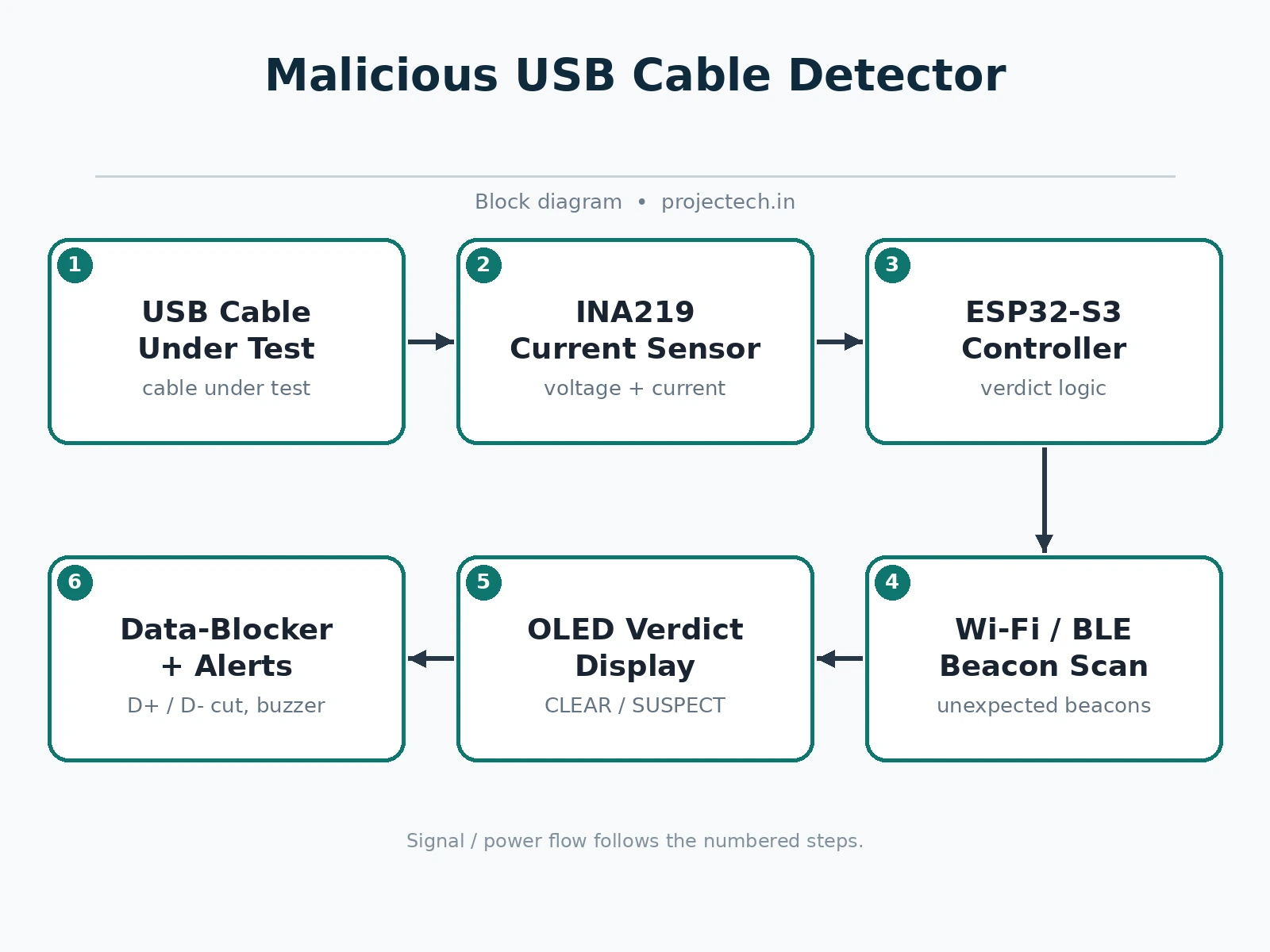
A scan works like this. The student first records a baseline: a plain charging cable from a known source is plugged through the detector, and the firmware stores its idle draw, inrush spike and steady-state current. The cable under test is then connected in the same way, and the detector repeats the measurement while the ESP32's Wi-Fi and BLE radios sweep the air around it. The firmware compares the new readings with the baseline and checks whether any wireless network or advertisement appeared only during this test window. If current matches the baseline and nothing unexpected appears, the OLED shows CLEAR with the green LED. If current runs well above baseline, or an unexpected beacon shows up, the OLED shows SUSPECT with the red LED and buzzer, and the dashboard lists exactly which check failed. If the measurement is incomplete, the verdict is UNKNOWN, because an inconclusive test must never be reported as safe.
Sliding the data-blocker switch at any point disconnects the data lines, so a suspect cable can still deliver charging power while the student decides what to do with it. No attack cable is ever built: testing uses only the student's own cables plus a benign jig made from a BLE beacon and a resistor load.
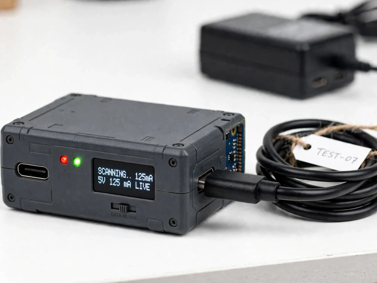
- The student assembles the handheld detector: ESP32-S3 board, INA219 current sensor module, 0.96-inch OLED, buzzer, red and green LEDs and a data-line slide switch, fitted in a small enclosure with USB-C in and out ports.
- A known-good plain charging cable is plugged through the detector and its idle draw, inrush and steady-state current are recorded as the baseline the verdicts are judged against.
- The cable under test is connected in the same way, and the detector measures its current profile while the ESP32 scans for nearby Wi-Fi networks and BLE advertisements.
- Firmware compares the new profile with the baseline and checks whether any wireless signal appeared only during this test window, then sets the verdict to CLEAR, SUSPECT or UNKNOWN.
- The verdict and its reasons appear on the OLED with the matching LED and buzzer signal, and the same result streams to the scan dashboard with the live current trace.
- The student verifies the detector itself using the benign test jig — a BLE beacon plus a resistor load — which must produce a SUSPECT verdict, proving the detector can catch the signals it claims to catch.
- Every scan is logged with its readings, flags and verdict, and the log is exported as CSV for the report; a suspect cable is quarantined or used only in data-blocker mode for charging.
Tech stack:
- ESP32-S3 microcontroller board (dual-core Xtensa LX7 at 240 MHz · Wi-Fi · BLE 5)
- INA219 current and voltage sensor module (I2C · 0 to 26 V bus range · 12-bit ADC)
- 0.96-inch SSD1306 OLED display (128 by 64 pixels · I2C · verdict readout)
- USB-C in and out ports with data-line slide switch (power passes · D+ and D- cut)
- Buzzer plus red and green LEDs (audible SUSPECT alert · bench verdict lights)
- Benign test jig (BLE beacon module · resistor load · no HID emulation)
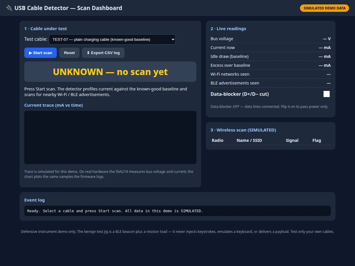
- Scan dashboard with CSV export (live current trace · wireless list · verdict log)
- 5 V USB bench supply and known-good baseline cable (baseline reference · test load)
| Parameter | Value |
|---|---|
| Reference system | WireBadger by Berkeley Varitronics Systems (BVS): commercial availability announced 20 Oct 2026; list price $1,249.00 (reported); sold via BVS, Amazon and Walmart; Special Mention in TIME's Best Inventions of 2026 (reported); reported detection: electrical current-consumption analysis plus Wi-Fi and BLE activity scanning; built-in USB-C data-disable switch (reported) |
| Threat context | Malicious cables can hide electronics inside an ordinary-looking cable; the O.MG Cable is an authorized penetration-testing tool that demonstrates the class of attack at concept level (reported) — this project never builds or uses one |
| Student detector | Handheld ESP32-S3 unit in a small enclosure (design target: about 90 mm by 55 mm by 25 mm) with USB-C input port, USB-C output port, 0.96-inch OLED, buzzer, red LED, green LED and data-line slide switch |
| Microcontroller | ESP32-S3: dual-core Xtensa LX7 up to 240 MHz, 2.4 GHz Wi-Fi (802.11 b/g/n) and Bluetooth 5 LE (manufacturer datasheet values) |
| Current sensing | INA219: bus voltage range 0 to 26 V, 12-bit ADC, I2C interface, supply 3 V to 5.5 V (manufacturer datasheet values); typical module shunt 0.1 ohm (manufacturer module value) |
| Display | SSD1306 OLED: 128 by 64 pixels, I2C interface, 3.3 V supply (manufacturer datasheet values); shows verdict plus current and flag reasons |
| USB power path | USB 2.0 power: 5 V nominal; USB 2.0 unit load 100 mA and up to 500 mA for a standard downstream port (USB specification values); detector passes through the charger or host supply |
| Verdict logic | CLEAR: current within baseline tolerance and no unexpected wireless signal; SUSPECT: steady-state current above the calibrated threshold or an unexpected Wi-Fi/BLE signal during the test window; UNKNOWN: incomplete or unstable measurement (design-target logic, thresholds calibrated by the student) |
| Data blocker | Physical slide switch disconnects USB D+ and D- data lines; 5 V power lines (VBUS and GND) stay connected, so charging continues with no data path (design description) |
| Wireless scan | ESP32 Wi-Fi scan plus BLE advertisement scan during each test window; a signal counts as unexpected only if it appears during the test window and was absent from the pre-test sweep (design-target rule) |
| Safety rule | The student NEVER builds a real attack cable: the only test jig is a benign BLE beacon plus a resistor load; no keystroke injection, no HID emulation, no payload delivery, no covert exfiltration; testing uses only the student's own cables and the benign jig, never anyone else's device |
| Measured results | Baseline current, test current, inrush peak, wireless flags and verdict per scan — all logged to CSV by the student during testing (no results pre-claimed) |
| Honest boundary | A SUSPECT verdict is evidence of anomalous behaviour, not proof of malicious intent: a faulty cable or a nearby beacon can also trigger it, and the report must state this limit plainly |
Project features
The detector's capabilities are seven. First, current profiling: the INA219 measures bus voltage and current through the cable and compares idle draw, inrush and steady-state draw against a stored known-good baseline. Second, wireless-beacon scanning: the ESP32's Wi-Fi and BLE radios list nearby networks and advertisements, flagging any that appear only while the suspect cable is connected. Third, a three-state verdict: CLEAR, SUSPECT or UNKNOWN, always shown with its reasons on the OLED and in the dashboard, never as a bare colour. Fourth, a physical data-blocker switch: sliding it disconnects the D+ and D- data lines while power keeps flowing, so a suspect cable can charge safely. Fifth, audible and visual alerts: a buzzer plus red and green LEDs repeat the verdict for bench use. Sixth, a verdict log: every scan is recorded and exported as CSV. Seventh, a working scan dashboard: the laptop or phone view shows the live current trace, the wireless scan list and the verdict history.
- [Current profiling] An INA219 sensor measures the cable's bus voltage and current, then compares idle draw, inrush and steady-state draw against a stored known-good baseline — hidden electronics betray themselves by drawing current a plain cable never draws.
- [Wireless-beacon scanning] The ESP32-S3's own Wi-Fi and BLE radios scan during the test and flag any network or advertisement that appears only while the cable under test is connected, mirroring WireBadger's reported wireless check.
- [Three-state verdict with reasons] Every scan ends in CLEAR, SUSPECT or UNKNOWN on the OLED and dashboard, always accompanied by the readings and flags behind it — a verdict without reasons is treated as a failed result in this build.
- [Physical data-blocker switch] A slide switch physically disconnects the USB D+ and D- data lines while 5 V power keeps flowing, so a cable that fails the scan can still charge a device with no data path at all.
- [Buzzer and LED alerts] A buzzer sounds on a SUSPECT verdict while the red LED lights; a CLEAR verdict lights the green LED, so the result is readable across a lab bench without opening the dashboard.
- [Verdict log with CSV export] Each scan stores its baseline, peak and steady-state current, wireless flags and verdict, and the dashboard exports the full log as CSV for the report's results section.
- [Working scan dashboard] The dashboard (working demo UI included) shows the live current trace, the wireless scan list, the data-blocker state and the verdict history, with a benign-jig test mode that demonstrates a SUSPECT result on demand.
What is included
- Assembled handheld detector: ESP32-S3 board, INA219 sensor module, 0.96-inch OLED, buzzer, red and green LEDs, data-line slide switch, USB-C ports and enclosure
- Scan dashboard app: live current trace, wireless scan list, verdict history, data-blocker indicator and CSV export (working demo UI included)
- Benign test jig: BLE beacon module plus resistor load, with a test procedure card that proves the detector catches a simulated rogue
- Wiring diagram and detector assembly layout with baseline-calibration procedure
- Component list with Indian supplier sourcing notes for the ESP32-S3 board, INA219 module, OLED and enclosure
- Project report PDF (malicious-cable threat at concept level, current-profiling method, wireless scanning, verdict logic, honest limits)
- PPT presentation for final review
- Viva Q&A preparation document (USB power and data lines, current profiling, BLE advertising, why a verdict is evidence and not proof, defensive testing ethics)
Limitations & prerequisites
- A SUSPECT verdict is not proof of malice: a damaged cable, a noisy supply or an unrelated beacon nearby can produce the same signals, so the report must present verdicts as evidence graded by corroboration, never as a definitive accusation against a cable.
- The student build cannot match WireBadger's commercial multi-stage pipeline: it samples current at bench accuracy and scans with the ESP32's own radios, so a well-hidden implant that draws almost no current and stays radio-silent between bursts could pass unnoticed — the report states this detection gap openly.
- The detector tests cables, not chargers or hosts: a compromised charger, a hostile USB port or malware already on the host are outside this instrument's scope, and the page claims nothing about them.
- Baseline quality decides verdict quality: a baseline recorded from a cable that is itself abnormal, or under an unstable supply, produces misleading verdicts, so the calibration procedure and its repeat runs are part of the deliverable, not an afterthought.
- The data-blocker switch protects the data path only: it cannot stop a faulty cable from delivering wrong voltage, and it is not a substitute for using trusted chargers — the report's safety section states this plainly.
- SAFETY HARD RULE: the student NEVER builds a real attack cable. The test jig is a benign simulated rogue only — a BLE beacon advertising a test name plus a resistor load that draws extra current. No keystroke injection, no HID emulation, no payload delivery, no covert exfiltration. The detector is a defensive instrument; testing uses only the student's own cables and the benign jig, never anyone else's device.
- Professional kit vs student jig — an explicit distinction: BVS offers professionals an optional Test Cable Kit with clearly labelled known-good cables alongside known malicious cables (including O.MG) for professional demos. That kit is for trained professionals working under authorization, and it does NOT transfer to this student build: the student must NOT obtain, borrow or test with a real malicious cable under any circumstances. The student test jig stays a benign simulated rogue (BLE beacon name + resistor load only), and any report, demo or viva answer that suggests otherwise is wrong.
- Wireless scanning sees advertisements, not intent: a BLE beacon's name and signal strength say nothing certain about what device owns it, so an unexpected beacon is a flag for quarantine, not an identification.
Frequently Asked Questions
What is WireBadger, and why did it inspire this project?
WireBadger is a commercial malicious-cable detector from Berkeley Varitronics Systems, whose availability was announced on 20 October 2026 and which earned a Special Mention in TIME's Best Inventions of 2026. It checks a cable by analysing its electrical current consumption and scanning for suspicious Wi-Fi and Bluetooth Low Energy activity, with a built-in USB-C data-disable switch. It inspired this project because its two detection ideas — current profiling and wireless scanning — can be reproduced honestly at student scale with an ESP32-S3 and an INA219 sensor, turning a news story about a security tool into a measurable defensive instrument.
How does current profiling catch a hidden device inside a cable?
A plain charging cable draws almost nothing on its own: the current it passes goes to the device being charged, and its idle draw is near zero. Hidden electronics inside a doctored cable need power for themselves, so they add their own idle draw and change the inrush and steady-state shape of the current trace. The detector records a known-good cable's trace first, then compares the cable under test against it; a steady draw far above the baseline is the anomaly that, together with a wireless flag, produces a SUSPECT verdict.
What does the wireless scan actually look for?
The scan looks for Wi-Fi networks and BLE advertisements that appear only while the cable under test is connected. A doctored cable that talks wirelessly must advertise or beacon to be reachable, and that signal is a second, independent channel of evidence beyond current draw. The detector first sweeps the air with no cable connected, then sweeps again during the test, and only signals new to the second sweep count as unexpected — so the student's own phone or lab router does not trigger a false flag.
Does the data-blocker switch make any cable safe to use?
No — it makes a suspect cable safe to charge from, which is a narrower and honest claim. The switch physically disconnects the D+ and D- data lines while 5 V power keeps flowing, so no data can travel between the cable and the host. It does not fix a faulty cable, it does not correct wrong voltage, and it does not make a suspect cable safe for data transfer; data use stays forbidden until a cable passes the full scan.
Is this a strong choice for a final-year submission?
Yes — for Electronics, IoT and related programs, because it combines four defensible engineering layers in one build: precision current sensing, wireless scanning on a microcontroller, verdict logic with calibrated thresholds, and a physical safety control. It also demonstrates defensive security thinking — baseline, corroboration and a safe default — which examiners can probe deeply, and its honest limits (verdict as evidence, not proof) give the report a credibility that a claimed-perfect detector would lack.
Components & software requirements
- ESP32-S3 microcontroller board (dual-core Xtensa LX7 at 240 MHz · Wi-Fi · BLE 5)
- INA219 current and voltage sensor module (I2C · 0 to 26 V bus range · 12-bit ADC)
- 0.96-inch SSD1306 OLED display (128 by 64 pixels · I2C · verdict readout)
- USB-C in and out ports with data-line slide switch (power passes · D+ and D- cut)
- Buzzer plus red and green LEDs (audible SUSPECT alert · bench verdict lights)
- Benign test jig (BLE beacon module · resistor load · no HID emulation)
- Scan dashboard with CSV export (live current trace · wireless list · verdict log)
- 5 V USB bench supply and known-good baseline cable (baseline reference · test load)
Delivery information
Built-to-order project. Delivery timeline is shared after order confirmation based on current queue.
Support terms
Complete documentation, setup guide, and viva preparation included. Support for setup and explanation provided.
Download free synopsis (PDF)
Enter your name and WhatsApp number — the synopsis PDF downloads immediately. We may send occasional project updates on WhatsApp; no spam.