
More project photos (2)
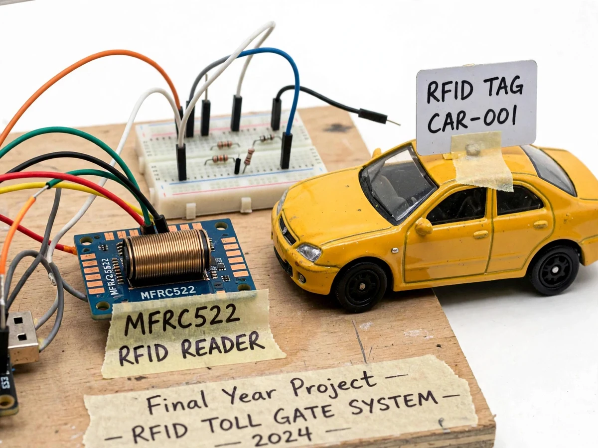
The problem
Toll plazas are choke points. Every vehicle that stops to pay adds seconds of delay, and those seconds compound across thousands of vehicles into long queues, wasted fuel and idling emissions — at plazas built to keep traffic moving. Manual collection also leaks revenue: cash is hard to audit, change-making slows the lane, and the whole operation depends on an attendant being present and alert. Electronic tolling solves the payment, but a tag alone is not a system — the plaza must still identify the vehicle, verify it can pay, open the barrier, and log the transaction for audit. That is an identification-plus-billing-plus-actuation problem, which maps neatly onto embedded hardware: a contactless reader for identity, a prepaid wallet in firmware for billing, a servo barrier for actuation, and a cloud log so every deduction is traceable. At tabletop scale it demonstrates the complete transaction pipeline real ETC systems run.
How it works
- A vehicle carrying an RFID tag approaches the plaza within the reader's zone.
- The EM-18 reader captures the tag's unique ID and sends it to the microcontroller over UART.
- The firmware looks up the tag in its registered-vehicle table and checks the prepaid balance.
- If the tag is valid and funded, the toll is deducted, the servo lifts the barrier arm, and the OLED confirms the deduction.
- The transaction (tag ID, vehicle number, amount, balance, timestamp) is pushed over WiFi to the dashboard log.
- Invalid tags or low balances trigger the buzzer and a dashboard alert; the operator can use manual override.
Project features
- Contactless vehicle identification with EM-18 125 kHz RFID reader (8–12 cm read range)
- Prepaid wallet logic — toll auto-deducted from each tag's registered balance
- Servo-driven barrier arm lifts in ~1 s after successful payment (design target)
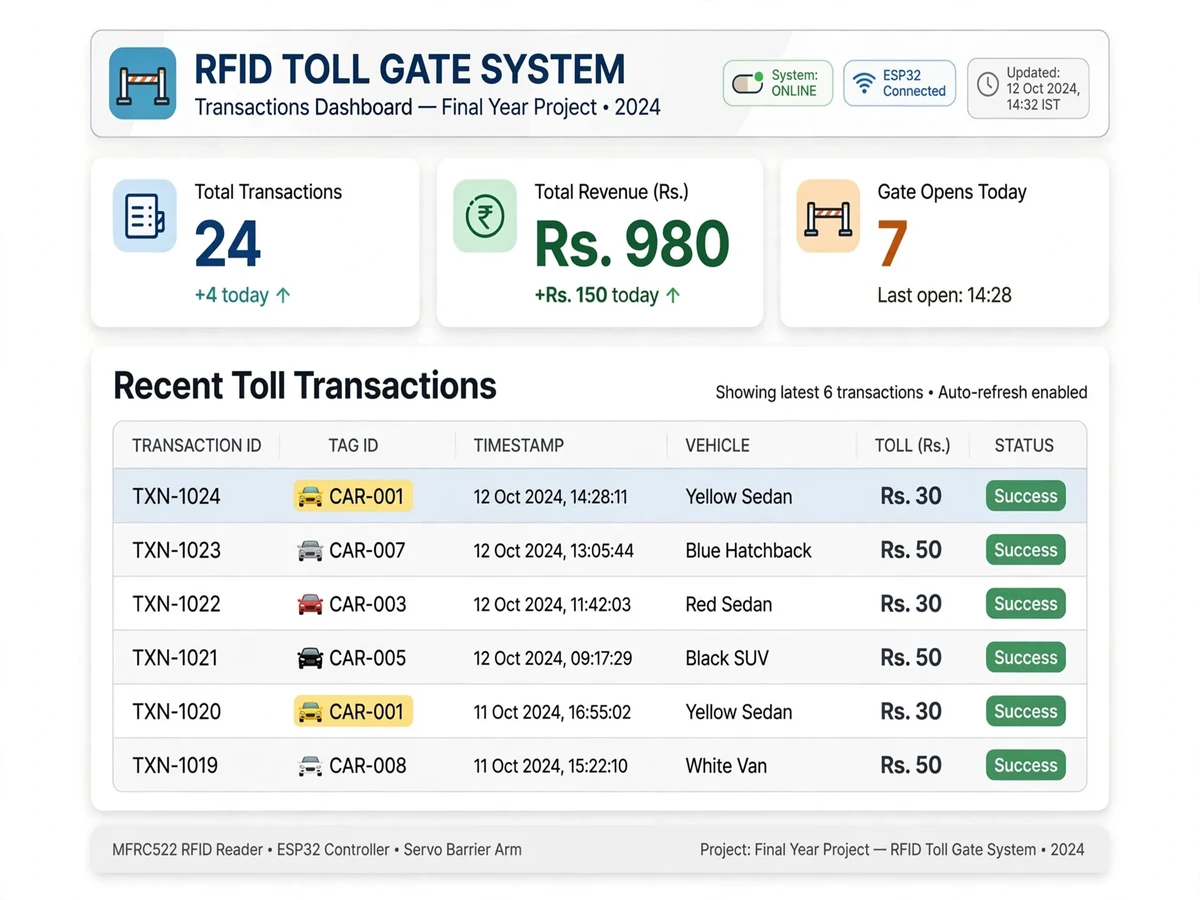
- Live web dashboard with transaction history, vehicle log and balance table
- Low-balance warnings and invalid/unknown-tag alerts with buzzer
- On-plaza 0.96" OLED display showing vehicle ID, toll and remaining balance
- Manual override button for unregistered vehicles
- Multi-lane logic support — one controller can serve two reader/barrier pairs
- Toll-rate table (car vs. truck pricing) to demonstrate fare classes
What is included
- Assembled toll-plaza prototype with booth, barrier gantry and lane markings
- Complete source code (Arduino IDE, well-commented)
- Circuit diagram and wiring schematic
- Project report PDF (synopsis, design, results, conclusion)
- PPT presentation for final review
- Viva Q&A preparation document
- RFID tags pre-registered as demo vehicles with starter balances
FAQs
- What does this project cover technically? RFID communication, embedded control, wallet and billing logic, UART protocols and cloud transaction logging — mapping to ECE, EEE and CSE (IoT) coursework. The report and viva Q&A document each part.
- How is this different from real FASTag? Real FASTag uses UHF RFID with long-range readers and bank-linked wallets. This prototype demonstrates the same end-to-end flow — tag identification, balance deduction, barrier control, transaction logging — at demo scale with the EM-18 module. The report prepares you to discuss the comparison.
- What happens if a tag has insufficient balance? The barrier stays down, the red LED and buzzer activate, and the dashboard raises a low-balance alert. The manual-override button lets the demo continue — a realistic touch.
- Can I register more vehicles? Yes — the firmware holds a registry of tag IDs with vehicle numbers and balances, and the dashboard setup guide shows how to add vehicles and top up wallets.
- Does it work without internet? Yes — RFID reading, deduction, barrier and OLED all run locally. Only the cloud transaction log needs WiFi; a phone hotspot is fine for demos.
- What are sensible extensions? ANPR camera integration, UHF long-range readers, SMS receipts via GSM, and toll-rate classes by vehicle type. The report lists them as future scope.
Limitations & prerequisites
- The EM-18 read range (8–12 cm) means demo vehicles must pass close to the reader — full-size plazas use long-range UHF readers; the report documents this difference for review readiness.
- Prepaid balances are stored in the prototype's local database — a production system would need a secure central server.
- A stable 2.4 GHz WiFi connection is needed for cloud logging; barrier operation and the OLED work offline.
- Supports one lane per reader out of the box; multi-lane needs additional readers.
Components & software requirements
- ESP32 DevKit (WiFi) — Arduino Uno variant available
- EM-18 125 kHz RFID reader (TTL UART)
- RFID tags/cards (EM4100, pre-registered as demo vehicles)
- SG90 / MG90S servo with barrier arm
- 0.96" SSD1306 OLED display (I2C)
- Active buzzer + status LEDs
- Tabletop toll-plaza model
- Web dashboard (transaction log, wallet table)
Specifications
| Parameter | Value |
|---|---|
| Microcontroller | ESP32 (240 MHz, WiFi 802.11 b/g/n) or Arduino Uno |
| RFID reader | EM-18, 125 kHz, TTL UART @ 9600 baud |
| Read range | 8–12 cm (card), ~5 cm (keychain fob) |
| Tag format | EM4100-compatible, 10-digit unique ID |
| Barrier servo | SG90 (1.8 kg·cm) / MG90S (2.2 kg·cm), ~1 s lift time |
| Transaction time | <2 s from tag read to barrier lift |
| Display | 0.96" OLED, 128×64 — ID, toll, balance |
| Telemetry | WiFi; MQTT/HTTP to dashboard |
| Power | 5 V / 2 A adapter; reader draws ~50 mA active |
| Dashboard | Live transactions, vehicle registry, balance table, alerts |