
More project photos (2)
The problem
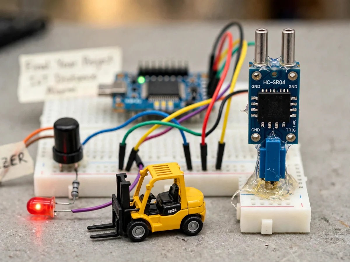
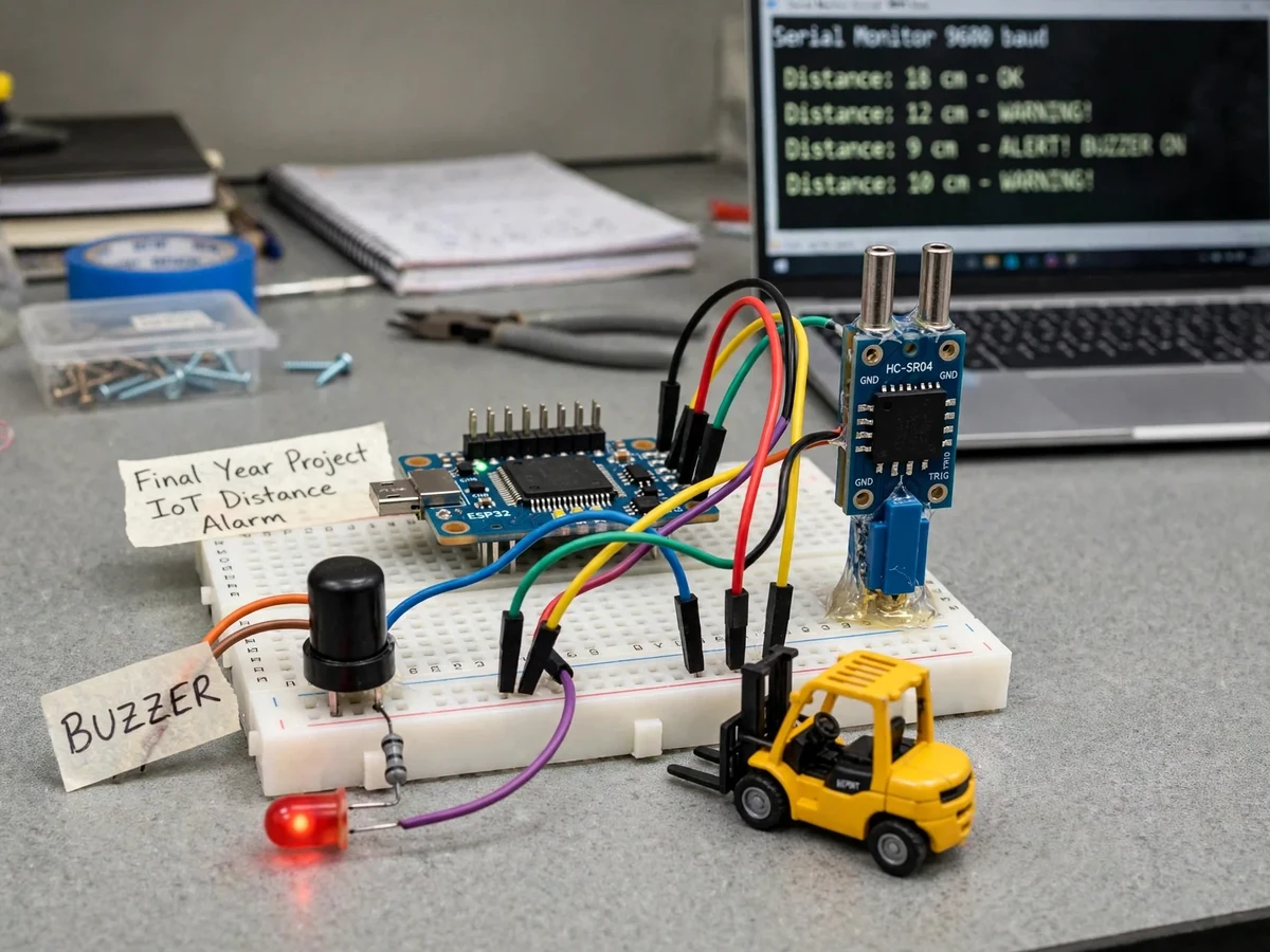
Forklifts and pedestrians sharing the same floor are one of the oldest hazards in warehouses: blind corners, racking aisles and loading docks create exactly the situations where a few meters of early warning prevent an accident. Industrial proximity systems exist but are expensive and closed; this project shows the sensing-and-alert loop can be built from commodity parts. An HC-SR04 ultrasonic sensor watches the approach zone and an ESP32 converts echo timing into distance, comparing it against configurable warning and danger thresholds. Crossing a threshold escalates the local response — LED, then buzzer — while every reading and alert event is published over Wi-Fi to a lightweight web dashboard with a live distance readout and an event log. The prototype is demonstrated at bench scale (a model forklift as the target), which keeps the physics identical while the build stays affordable and explainable. Threshold calibration is a documented procedure, so the report's zone settings come from the student's own measurements. This is a built-to-order hardware project: the prototype is assembled, wired and calibrated fresh for your order.
How it works
- The HC-SR04 emits an ultrasonic ping; the ESP32 measures the echo return time and converts it to distance (distance = echo time × 0.034 / 2).
- Each reading is compared against the configured warning and danger thresholds.
- Inside the warning zone the red LED blinks; inside the danger zone the buzzer sounds and the LED goes solid.
- Readings and zone state are published over Wi-Fi to the web dashboard, which shows the live distance and logs alert events.
- The serial monitor prints every threshold crossing with its distance for the report's test table.
- Thresholds are tuned with the calibration procedure: the student measures real distances and sets the constants in firmware.
Tech stack:
- ESP32 DevKit (Wi-Fi microcontroller)
- HC-SR04 ultrasonic distance sensor
- Piezo buzzer module
- Red LED indicator
- Arduino IDE (firmware)
- Wi-Fi + lightweight web dashboard (live distance & event log)
- 5 V USB power supply
| Parameter | Value |
|---|---|
| Controller | ESP32 DevKit |
| Sensor | HC-SR04 ultrasonic, 2–400 cm (datasheet range) |
| Zones | Warning / danger distances, configurable in firmware (design values set during calibration) |
| Local alert | Piezo buzzer + red LED |
| Dashboard | Web dashboard over Wi-Fi: live distance, zone state, event log |
| Alert latency | Design target under 1 second from detection to buzzer |
| Power | 5 V USB |
| Demo scale | Bench prototype (model forklift as target) |
Project features
- [Ultrasonic distance sensing] HC-SR04 measures target distance continuously (design target: 2–400 cm per the sensor datasheet) from echo timing.
- [Zone-based escalation] Configurable warning and danger distances: LED blink at warning, buzzer + LED at danger.
- [Local audible/visual alarm] Buzzer and red LED fire directly from the ESP32 — no Wi-Fi needed for the core alert.
- [Wi-Fi alert dashboard] Live distance, current zone and an alert event log published to a simple web dashboard over Wi-Fi.
- [Threshold calibration] Documented procedure for setting warning/danger distances from real measured readings.
- [Serial event log] Every threshold crossing is printed to the serial monitor for capture into the report.
What is included
- Assembled and calibrated working prototype (ESP32, HC-SR04, buzzer, LED)
- Complete firmware source code (sensing, zones, dashboard publishing)
- Web dashboard code with setup instructions
- Circuit/wiring documentation with connection diagram
- Component list with sourcing notes
- Threshold calibration procedure
- Project report PDF (background, methodology, measured zone data)
- PPT presentation for final review
- Viva Q&A preparation document (ultrasonic sensing, ESP32, Wi-Fi dashboards, threshold design)
Limitations & prerequisites
- The HC-SR04's datasheet range is 2–400 cm and its readings depend on surface angle and material — soft, angled or very small targets read unreliably, which the report documents.
- This is a bench-scale academic prototype demonstrated with a model forklift. Real-vehicle deployment would need industrial-grade sensors, weatherproofing and safety certification — explicitly out of scope.
- The dashboard needs Wi-Fi in range; the local buzzer/LED alerts work without any network.
- Alert latency is a design target (under 1 s), not a certified response time — this is not a safety-rated system.
- Ultrasonic sensors can cross-talk if several operate nearby; the guide notes single-sensor placement.
Frequently Asked Questions
Which controller is used?
An ESP32 DevKit — its built-in Wi-Fi carries the dashboard feed, and the firmware is written in the Arduino IDE.
Does it work without Wi-Fi?
The local alert (buzzer + LED) works with no network at all. Only the web dashboard needs Wi-Fi.
What power supply is needed?
Any 5 V USB source — a phone charger or power bank runs the whole prototype.
Can the alert distances be changed?
Yes — warning and danger thresholds are constants in the firmware, set using the documented calibration procedure with real measured distances.
What are the main limitations?
Sensor range/angle dependence, bench-scale demo (not a certified vehicle safety system), and Wi-Fi dependence for the dashboard. Details are in Limitations & Prerequisites above.
Is this project suitable for a final-year project?
Yes — for IoT, Electronics and Electrical programs. It demonstrates ultrasonic sensing, threshold logic, ESP32 Wi-Fi and dashboard publishing, with the report built on the student's own calibration data. Suitable for B.E./B.Tech final-year projects in IoT, Electronics and Electrical Engineering.
Components & software requirements
- ESP32 DevKit (Wi-Fi microcontroller)
- HC-SR04 ultrasonic distance sensor
- Piezo buzzer module
- Red LED indicator
- Arduino IDE (firmware)
- Wi-Fi + lightweight web dashboard (live distance & event log)
- 5 V USB power supply
Delivery information
Built-to-order project. Delivery timeline is shared after order confirmation based on current queue.
Support terms
Complete documentation, setup guide, and viva preparation included. Support for setup and explanation provided.