
More project photos (2)
The problem
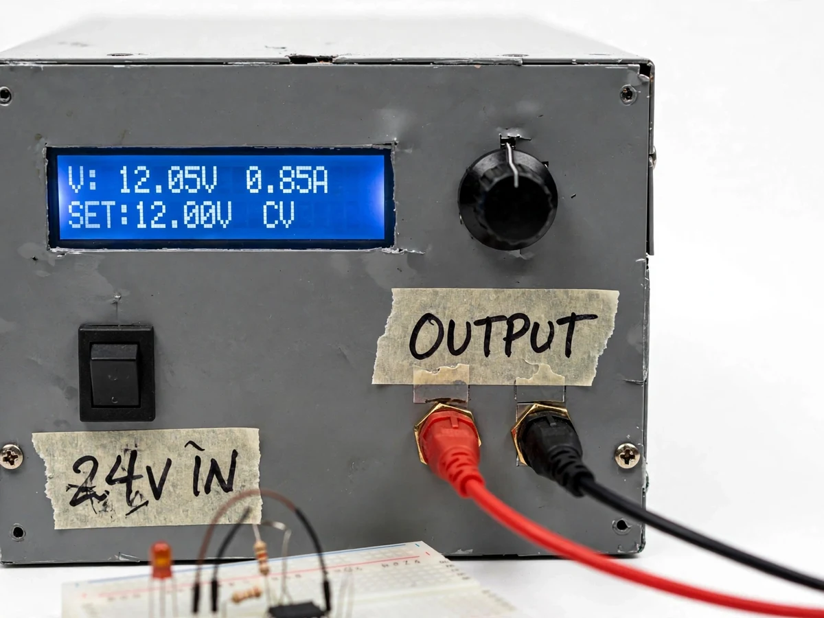
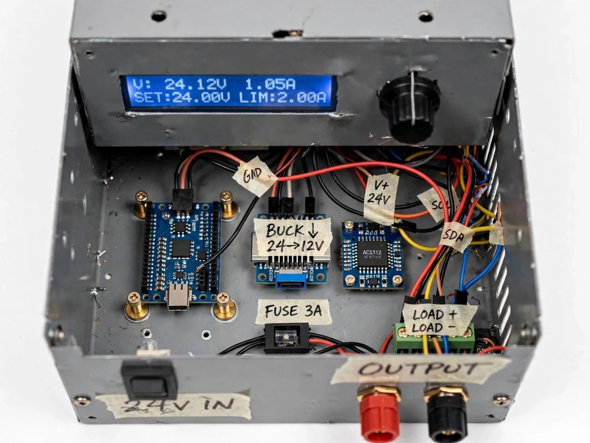
Every electronics student eventually needs a variable bench supply: wall adapters give one fixed voltage, linear regulators waste power and still fix the voltage, and powering a prototype at the wrong voltage destroys boards. Commercial CC-CV bench supplies are priced beyond a typical student budget, and cheap adapters give no current limiting — one shorted wire means burnt traces. This project builds a digital bench variable DC power supply around an Arduino Nano. A rotary encoder sets the output in 0.1 V steps (design value), a 16×2 LCD shows set and measured voltage, load current and the active mode, and the firmware implements true CC-CV behavior: constant voltage until the load current reaches the programmed limit, then constant current as the voltage sags. Short circuits latch the output off until reset. It is an explainable instrument — the student can describe the buck stage, feedback injection, current sensing and firmware loop in a viva without hand-waving.
Each detent changes the voltage setpoint by 0.1 V; a press switches to the current-limit setpoint.
Follow the working sequence
How it works
- The operator turns the rotary encoder; each detent changes the voltage setpoint by 0.1 V (design value), and a button press switches the encoder to the current-limit setpoint (0–3 A range, design target).
- A firmware control loop running approximately every 10 ms (design target) converts the voltage setpoint into a PWM duty cycle; an RC low-pass filter (1 kΩ, 10 µF — design values) smooths this into a DC control voltage injected into the buck converter's feedback node.
- The output voltage is sampled through a resistor divider scaled for the Nano's 10-bit ADC using its internal 1.1 V reference (datasheet); the loop trims the PWM to hold the measured voltage at the setpoint — this is constant-voltage mode.
- Load current is measured by an ACS712 Hall-effect sensor (±5 A variant, 185 mV/A — datasheet) and scaled to amperes in firmware; output power is computed from V × I.
- When the measured current reaches the set limit, the firmware switches to constant-current mode: it reduces the PWM drive to hold current constant, the LCD mode flag flips from CV to CC, and the output voltage sags as the load demands.
- On a sudden over-current spike — a shorted load — the firmware latches the converter off, raises a fault message on the LCD, and requires a manual reset; the 3 A slow-blow input fuse (design value) provides hardware backup.
- Four EEPROM presets (3.3/5/9/12 V defaults, user-rewritable) are recalled with the encoder button for the voltages students reach for most often.
Tech stack:
- Arduino Nano (ATmega328P)
- Arduino IDE (C++ firmware)
- DC-DC buck converter module (adjustable)
- ACS712 current sensor
- 16×2 LCD (HD44780)
- Rotary encoder
- 24 V SMPS input adapter
- Perfboard wiring
| Parameter | Value |
|---|---|
| Output voltage range | 0–24 V (design target; input must stay ~2 V above output — expected) |
| Current limit range | 0–3 A (design target, bounded by module rating and wiring) |
| Voltage setting step | 0.1 V (design value) |
| Current limit step | 0.1 A (design value) |
| Voltage display resolution | 0.1 V (design value) |
| Current display resolution | Approximately 0.01 A (expected) |
| Control loop period | Approximately 10 ms (design target) |
| ADC | 10-bit, ATmega328P internal 1.1 V reference (datasheet) |
| Current sensor | ACS712 ±5 A variant, 185 mV/A sensitivity (datasheet) |
| Feedback drive | PWM → RC low-pass (1 kΩ, 10 µF — design values) into buck FB node |
| Input supply | 24–30 V DC SMPS brick (design value) |
| Input fuse | 3 A slow-blow (design value) |
| Presets | 4 EEPROM voltage presets, user-rewritable (design value) |
| Enclosure | Ventilated metal prototype box; Approximately 200 × 150 × 80 mm (typical build) |
Project features
- [Digital voltage control] A rotary encoder sets the output in 0.1 V steps (design value) with the value taking effect live; pressing the encoder switches it to adjust the current limit instead.
- [True CC-CV modes] In constant-voltage mode the output holds the set voltage; when the load current reaches the programmed limit the firmware switches to constant-current mode, holding current steady while voltage sags. The LCD flags the active mode.
- [Live voltage and current readout] A 16×2 LCD shows the set voltage, the measured output voltage, the load current and the CV/CC indicator, refreshed approximately 4 times per second (design target).
- [Short-circuit protection] A sudden over-current event latches the converter output off and raises a fault screen until the user resets; a 3 A slow-blow input fuse (design value) backs up the firmware protection.
- [EEPROM voltage presets] Four user-rewritable presets (default 3.3, 5, 9 and 12 V) are stored in the Nano's EEPROM and recalled from the front panel, retained without power.
- [Multimeter calibration procedure] A documented two-point calibration against the buyer's reference multimeter stores calibration constants in EEPROM, so the displayed values match a real instrument.
- [Filtered-PWM feedback drive] The firmware turns one Nano PWM channel into a smooth control voltage through an RC low-pass filter (1 kΩ, 10 µF — design values) injected into the buck module's feedback node.
- [Prototype enclosure] A ventilated metal box with panel-mount binding posts, the LCD window, the encoder knob and handwritten masking-tape labels — a real bench instrument, not a breadboard demo.
What is included
- Working bench variable DC power supply prototype with digital control and CC-CV
- Arduino firmware source code with comments
- Circuit/wiring diagram and front-panel layout drawing
- Component list with values
- Two-point calibration procedure against a reference multimeter
- Project report PDF (design, firmware logic, calibration, results)
- PPT presentation for final review
- Viva Q&A preparation document (buck converters, CC-CV, feedback, ADC, current sensing)
- Demonstration guidance
Limitations & prerequisites
- Output maximum follows the input: 24 V out needs a 26–30 V input brick (expected), because the buck stage cannot boost above its input.
- Displayed voltage and current are only as accurate as the buyer's two-point calibration against their reference multimeter; some temperature drift is expected.
- 0–3 A is a design target bounded by the buck module rating and wiring gauge, not a measured thermal rating; sustained full-load operation needs the documented heatsinking and ventilation.
- The CC loop is a firmware loop (~10 ms, design target), not an analog control loop — it will not catch microsecond-scale transients; the input fuse is the fast protection.
- This is a prototype instrument, not a certified laboratory supply — no calibration certificate and no industrial/medical certification.
- Input ripple and load-transient response are module-dependent (component-dependent).
- High-current operation needs clear ventilation; the enclosure vents must not be blocked.
Frequently Asked Questions
Which controller is used?
An Arduino Nano (ATmega328P). It reads the rotary encoder, drives the buck module through a filtered-PWM control voltage, samples output voltage and current with its 10-bit ADC, runs the CC-CV loop, and updates the 16×2 LCD.
Is the current limiting real CC-CV?
Yes. CV mode holds the set voltage; when the load current reaches the programmed limit, firmware switches to CC mode and holds current constant while the voltage sags. A short circuit latches the output off until reset.
What feeds the supply?
A 24–30 V DC SMPS brick (design value), specified in the component list. The maximum output is about 2 V below the input because it is a buck stage.
Does it need calibration?
Yes — the deliverables include a two-point calibration procedure against a reference multimeter, and the firmware stores the calibration constants in EEPROM.
Can it be customized?
Yes: an OLED display in place of the 16×2 LCD, more presets, serial logging of V/I to a PC, temperature-based fan control, or a higher-current buck module (needs wiring and thermal redesign).
Is this project suitable for a final-year project?
Yes — for Electronics, E&TC, Electrical and Instrumentation programs. It demonstrates power electronics, feedback control, current sensing, embedded C and instrument design, all explainable end to end in a viva.
Components & software requirements
- Arduino Nano (ATmega328P)
- Arduino IDE (C++ firmware)
- DC-DC buck converter module (adjustable)
- ACS712 current sensor
- 16×2 LCD (HD44780)
- Rotary encoder
- 24 V SMPS input adapter
- Perfboard wiring
Delivery information
Built-to-order project. Delivery timeline is shared after order confirmation based on current queue.
Support terms
Complete documentation, setup guide, and viva preparation included. Support for setup and explanation provided.
Download free synopsis (PDF)
Enter your name and email — the synopsis PDF downloads immediately. We may send occasional project updates; no spam, unsubscribe anytime.