
More project photos (3)

The problem
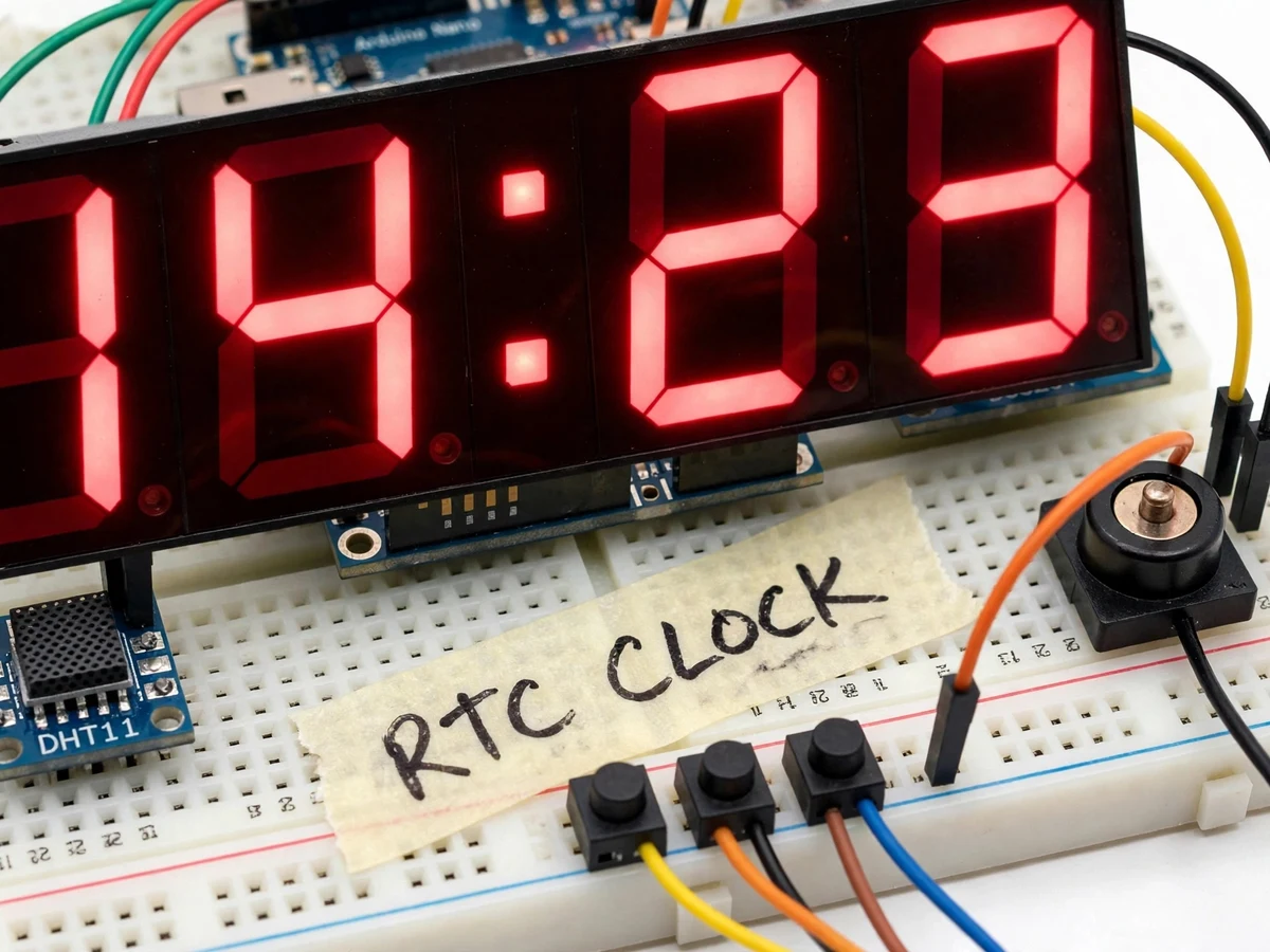
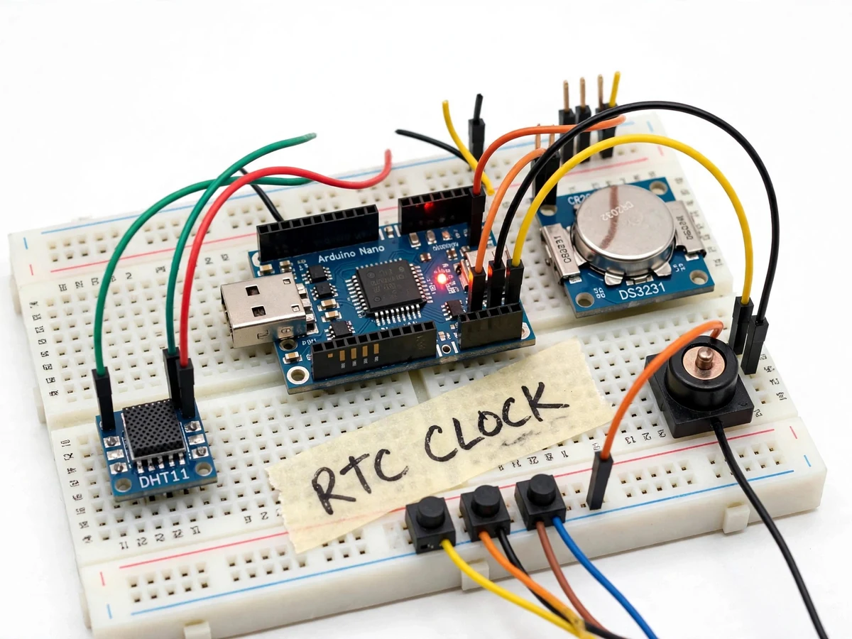
Every digital clock hides the same engineering question: where does accurate time come from? The Arduino's own oscillator drifts minutes per day — useless for a clock — which is why real designs use a dedicated real-time-clock chip with a temperature-compensated crystal. This project builds that proper architecture: a DS3231 RTC (specified ±2 ppm, roughly ±1 minute per year) keeps time over I2C, an Arduino multiplexes a large 4-digit 7-segment display, push buttons set time and alarm without a computer, a buzzer sounds the daily alarm, and a DHT11 sensor adds ambient temperature to the display cycle. Battery backup on the RTC keeps time through power cuts. It is a compact, honest embedded build where each subsystem — timekeeping, display, input, alarm — is a viva topic of its own.
Temperature-compensated timebase with coin-cell backup.
Follow the working sequence
How it works
- The DS3231's temperature-compensated crystal oscillator generates a stable 32.768 kHz timebase, counting seconds through years internally.
- The Arduino reads hours, minutes and seconds over I2C once per second using the RTC library.
- Firmware multiplexes the 4-digit 7-segment display — one digit enabled at a time, cycled fast enough to appear steady.
- Push buttons enter set mode: the blinking digit is adjusted up/down, stepping through hours, minutes, alarm time and 12/24-hour mode.
- Every second the firmware compares RTC time against the stored alarm; on match it drives the buzzer until the stop button is pressed.
- Every 10 seconds the display alternates to the DHT11 temperature reading for a few seconds, then returns to the time.
Tech stack:
- Arduino Nano (ATmega328P)
- DS3231 RTC module with coin-cell backup
- 4-digit 7-segment LED display (common cathode)
- DHT11 temperature sensor
- Buzzer + push buttons
- I2C RTC library, DHT library
- Arduino IDE (C/C++ firmware)
| Parameter | Value |
|---|---|
| Timekeeping | DS3231, ±2 ppm per datasheet (approximately ±1 min/year, design) |
| Display | 4-digit 7-segment, multiplexed, flicker-free refresh (design) |
| Alarm | Daily, button-set, buzzer with stop/snooze (design) |
| Temperature | DHT11, approximately ±2°C per datasheet (expected) |
| Backup | CR2032 cell keeps RTC through power cuts (design) |
| Modes | 12/24-hour, stored in EEPROM (design) |
| Power | 5 V USB or adapter (design) |
Project features
- [DS3231 precision RTC] A temperature-compensated RTC keeps time over I2C with a coin-cell backup that survives power cuts — the correct way to build a clock.
- [Large 4-digit 7-segment display] Bright multiplexed display readable across a room, driven with proper current limiting and flicker-free refresh.
- [Settable daily alarm] Time and alarm are set entirely with push buttons; the buzzer sounds at the alarm time with a snooze/stop button.
- [Temperature readout] A DHT11 sensor's reading alternates with the time on the display, adding a second live measurement to the build.
- [12/24-hour modes] Firmware supports both formats, switchable from the buttons, with the mode stored in EEPROM.
- [Power-fail timekeeping] The RTC's backup cell keeps counting during outages; on power return the display resumes the correct time automatically.
- [Low-part-count design] The whole clock runs from an Arduino Nano, the RTC, the display and a handful of passives — clean enough to explain fully in a viva.
What is included
- 4-digit 7-segment display module
- DS3231 RTC module with backup cell
- Arduino Nano with clock firmware
- DHT11 sensor, buzzer, setting buttons
- Enclosure-mounting guide and wiring diagrams
- Project report PDF (RTC timekeeping, I2C, multiplexing, alarm logic)
- PPT presentation for final review
- Viva Q&A preparation document
Limitations & prerequisites
- The ±2 ppm / ±1 min-per-year figure is the DS3231 datasheet specification, not a measured claim on the built unit.
- The DHT11's ±2°C is a datasheet value; this is an indicative room-temperature readout, not calibrated instrumentation.
- The alarm is a simple daily buzzer — no multiple alarms, no gradual volume, no radio; those are future scope.
- Display multiplexing means per-digit brightness is lower than static drive; it suits indoor viewing.
- Button setting has no PC sync; setting is manual, which the report frames as a deliberate design choice.
Frequently Asked Questions
Why use a separate RTC chip instead of the Arduino's timer?
The Arduino's ceramic resonator drifts minutes per day. The DS3231's temperature-compensated crystal holds ±2 ppm — the difference between a toy and a real clock.
Does it lose time in a power cut?
No — a coin cell on the RTC module keeps the chip counting; when power returns, the Arduino reads the correct time straight away.
How accurate is the temperature reading?
The DHT11 is specified at ±2°C — fine as an indicative room readout on the display, not as lab instrumentation, and the report states this honestly.
Can the alarm be set without a computer?
Yes — everything is set with the push buttons: time, alarm time and 12/24-hour mode, with the mode remembered in EEPROM.
Is this project suitable for a final-year project?
Yes — for Electronics and E&TC programs. It demonstrates RTC timekeeping, I2C, multiplexed displays, button UI design and alarm logic in one complete build. Suitable for B.E./B.Tech final-year projects in Electronics and E&TC.
Components & software requirements
- Arduino Nano (ATmega328P)
- DS3231 RTC module with coin-cell backup
- 4-digit 7-segment LED display (common cathode)
- DHT11 temperature sensor
- Buzzer + push buttons
- I2C RTC library, DHT library
- Arduino IDE (C/C++ firmware)
Delivery information
Built-to-order project. Delivery timeline is shared after order confirmation based on current queue.
Support terms
Complete documentation, setup guide, and viva preparation included. Support for setup and explanation provided.
Download free synopsis (PDF)
Enter your name and WhatsApp number — the synopsis PDF downloads immediately. We may send occasional project updates on WhatsApp; no spam.