
More project photos (2)
The problem
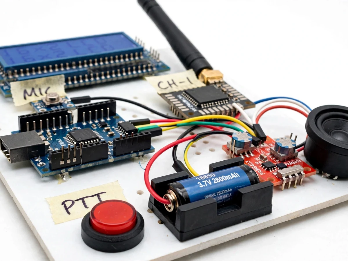
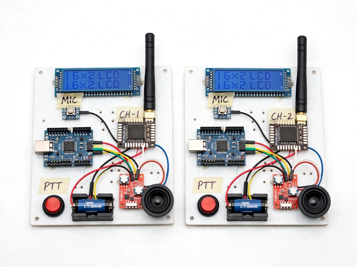
Electronics students study modulation, RF links and digital sampling in theory, yet most never build a radio that carries their own voice — the gap between the classroom and a working system stays wide. Hobby walkie-talkie tutorials usually stop at analog FM hacks or simply bounce data packets between two NRF24L01 modules and call it communication, skipping the real engineering: half-duplex push-to-talk state management, microphone gain control, ADC sampling discipline, channel selection and power budgeting for battery operation. This project closes that gap with two complete working handsets. Two Arduino Nanos digitize voice from MAX9814 AGC microphone modules at approximately 8 kHz, exchange 8-bit audio frames over NRF24L01+PA+LNA radios on a selected 2.4 GHz channel, and play the received audio through PAM8403 amplifiers and speakers. A 16x2 LCD shows the channel and TX/RX state; each unit runs on an 18650 cell charged via TP4056. The result is a demonstrable two-way radio link where every design decision — sampling rate, channel plan, TX/RX switching, audio chain — is visible and defensible.
Holds the handset, presses push-to-talk and speaks into the microphone.
Follow the working sequence
How it works
- The operator presses and holds the red push-to-talk button; firmware immediately switches the NRF24L01 from receive to transmit mode and routes the microphone chain to the ADC.
- The MAX9814 electret module applies automatic gain control to the voice signal, keeping quiet and loud speech inside the Nano's 0–5 V ADC window without manual level tweaking.
- The Nano samples the ADC at approximately 8 kHz and packs the 8-bit samples into 32-byte radio payloads queued in the module's transmit FIFO.
- The NRF24L01+PA+LNA transmits the payloads over the selected 2.4 GHz channel with GFSK modulation; the RF24 stack's hardware auto-acknowledgement and retransmission handle lost packets.
- On the receiving handset, an interrupt fires as each payload arrives; firmware unpacks the samples and writes them to a timer-driven PWM output, low-pass filtered and fed to the PAM8403 amplifier driving the 8-ohm speaker.
- Releasing the PTT button returns the unit to receive mode within a frame period; the LCD updates from TX back to RX.
- Both handsets must be set to the same channel; the channel buttons step through channels 1–16 and the LCD confirms the selection on each unit independently.
Tech stack:
- Arduino Nano (ATmega328P)
- NRF24L01+PA+LNA radio modules
- RF24 library with RF24Audio-style sampling
- MAX9814 AGC microphone module
- PAM8403 class-D amplifier
- 16x2 character LCD (HD44780)
- TP4056 Li-ion charger module
- Arduino IDE (C/C++ firmware)
| Parameter | Value |
|---|---|
| Controller | Arduino Nano, ATmega328P at 16 MHz |
| Radio module | NRF24L01+PA+LNA (Nordic nRF24L01+ core, datasheet) |
| Frequency band | 2.4 GHz ISM, 2.400–2.4835 GHz (datasheet) |
| RF channels | 126 available (datasheet); 16 selectable in firmware |
| Air data rates | 250 kbps / 1 Mbps / 2 Mbps, GFSK (datasheet) |
| Audio sampling | Approximately 8 kHz, 8-bit (design choice) |
| Audio chain | MAX9814 AGC mic → ADC → PAM8403 amp → 8 Ω speaker |
| Duplex mode | Half-duplex; one unit transmits at a time |
| Range | Up to approximately 1 km line-of-sight, open field (vendor specification; design target, not a measured claim) |
| Display | 16x2 character LCD (HD44780) |
| Power | One 18650 Li-ion cell (nominal 3.7 V) per handset |
| Charging | TP4056 module, 4.2 V / up to 1 A (datasheet) |
| Operating current | Approximately 130 mA during transmit with PA enabled (expected) |
Project features
- [Push-to-Talk Half-Duplex Protocol] Holding the PTT button switches the unit from receive to transmit; releasing it switches back. Firmware runs the TX/RX state machine — mic routing, speaker mute and radio mode switching — so there is no feedback loop or self-collision.
- [Approximately 8 kHz Digital Voice Sampling] The Nano samples the MAX9814 microphone output with its ADC at roughly 8 kHz and ships 8-bit audio frames over the radio, which the receiver reconstructs through PWM and filtering — real digitized speech, not an analog relay.
- [NRF24L01+PA+LNA Radio Link] 2.4 GHz ISM-band radios with external antennas; the PA+LNA front end raises the link budget. The design-target range is up to approximately 1 km line-of-sight in open field per the vendor specification — stated as a target, not a measured result.
- [16-Channel Selection] Sixteen selectable RF channels from the module's 126-channel capability, stepped with buttons and shown on the LCD — two pairs can converse on different channels in the same room without interfering.
- [16x2 LCD Status Display] The character LCD continuously shows the active channel number and the TX/RX state, so the operator always knows whether the unit is listening or transmitting.
- [PAM8403 Audio Output] A class-D amplifier module drives an 8-ohm speaker with a volume trimmer, giving clearly audible speech for classroom demonstrations without any external amplifier.
- [18650 Battery Power with USB Charging] Each handset runs on a single 18650 Li-ion cell; the TP4056 module recharges it from any USB port with built-in charge management.
- [Matched Handset Pair] Both units are built, channel-matched and audio-tested together before dispatch, so the two-way link works out of the box.
What is included
- Two assembled Arduino walkie-talkie handsets (working pair)
- Complete firmware source in C/C++ for both units (Arduino IDE)
- Circuit and wiring documentation with connection diagrams
- Component list with exact part numbers
- Channel-pairing and audio calibration procedure
- Project abstract PDF
- Project report PDF (RF theory, sampling design, protocol logic)
- PPT presentation for final review
- Viva Q&A preparation document
Limitations & prerequisites
- Half-duplex only: one side transmits at a time, so conversation needs turn-taking; both sides talking simultaneously is not supported.
- The 1 km figure is a vendor design target for open line-of-sight; walls, buildings and crowded 2.4 GHz Wi-Fi/Bluetooth spectrum reduce it substantially — a buyer-run range-test procedure is included in the documentation.
- 8 kHz 8-bit audio gives intelligible speech, not hi-fi sound; quantization noise and a short coding delay are inherent to the design.
- The 2.4 GHz ISM band is shared with Wi-Fi and Bluetooth, so heavy nearby traffic can cause audible dropouts on the link.
- Battery runtime depends on talk duty cycle, volume and the cell's mAh rating; no fixed runtime figure is claimed.
- The units are an academic prototype, not a certified radio product; applicable local regulations on 2.4 GHz transmission power should be checked before outdoor use.
Frequently Asked Questions
Which controller and radio does it use?
Two Arduino Nanos (ATmega328P) and NRF24L01+PA+LNA radio modules with external antennas. The Nano's 16 MHz ADC is fast enough for roughly 8 kHz sampling, and the PA+LNA front end provides the link budget the basic PCB-antenna module lacks.
How does push-to-talk work?
Press and hold the red PTT button to transmit; release it to receive. Firmware switches the radio between TX and RX modes and mutes the speaker while transmitting, so there is no acoustic feedback. Only one side can talk at a time — that is half-duplex, exactly like real walkie talkies.
What will the voice sound like?
Clear, intelligible speech: the voice is digitized at roughly 8 kHz in 8-bit samples. It is designed for conversation, not music — expect some digital grain at high volume, while the MAX9814 AGC keeps quiet and loud voices at a consistent level.
What range can I expect?
The PA+LNA variant's vendor specification targets up to approximately 1 km in open line-of-sight — a design target, not a measured claim. Indoors, through walls, or near strong Wi-Fi, range drops sharply; the documentation includes a step-by-step range test to run on your own pair.
What power supply does each handset need?
One 18650 Li-ion cell (nominal 3.7 V) per handset, recharged over USB through the TP4056 charger module. No bench supply is needed for normal use.
Is this project suitable for a final-year project?
Yes — for Electronics, E&TC, Electrical and IoT & Embedded programs. It demonstrates RF communication, digital audio sampling, embedded protocol design and power budgeting, and the report documents every design decision for the viva.
Components & software requirements
- Arduino Nano (ATmega328P)
- NRF24L01+PA+LNA radio modules
- RF24 library with RF24Audio-style sampling
- MAX9814 AGC microphone module
- PAM8403 class-D amplifier
- 16x2 character LCD (HD44780)
- TP4056 Li-ion charger module
- Arduino IDE (C/C++ firmware)
Delivery information
Built-to-order project. Delivery timeline is shared after order confirmation based on current queue.
Support terms
Complete documentation, setup guide, and viva preparation included. Support for setup and explanation provided.
Download free synopsis (PDF)
Enter your name and email — the synopsis PDF downloads immediately. We may send occasional project updates; no spam, unsubscribe anytime.