
More project photos (2)
The problem
Wireless communication is taught almost entirely through radio-frequency examples — Wi-Fi, Bluetooth, GSM — while visible light communication gets only a mention in passing. Yet the underlying ideas (modulation, carrier, receiver sensitivity, noise) are identical, and light has properties radio does not: it is confined by walls, immune to RF interference, and free of spectrum licensing. Students rarely build an actual free-space optical link because the analog front end looks intimidating: a photodiode produces tiny currents that must be amplified cleanly before a microcontroller can read them. This project closes that gap with a complete, demonstrable Li-Fi link — text typed into the transmitter appears on the receiver's LCD, carried entirely by light. It is a clean fit for communication-theory courses, embedded systems subjects, and optoelectronics electives, and it demos reliably on an examination table.
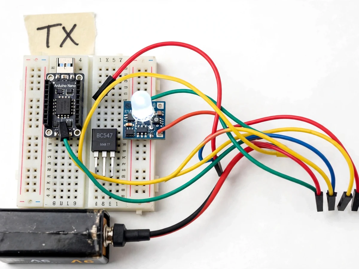
Transmitter Nano converting typed text to a binary bit stream.
Follow the working sequence
How it works
- The user enters a text string on the transmitter Arduino (via the serial monitor), which converts each character to its 8-bit binary form.
- The Nano toggles a digital pin at the configured data rate, driving the BC547 transistor so the high-brightness LED flashes the bit stream as light pulses.
- Across the free-space gap, the photodiode on the receiver converts arriving light pulses into small photocurrents.
- The LM358 transimpedance amplifier turns those tiny currents into rail-to-rail voltage swings, and a comparator stage slices them into clean digital pulses.
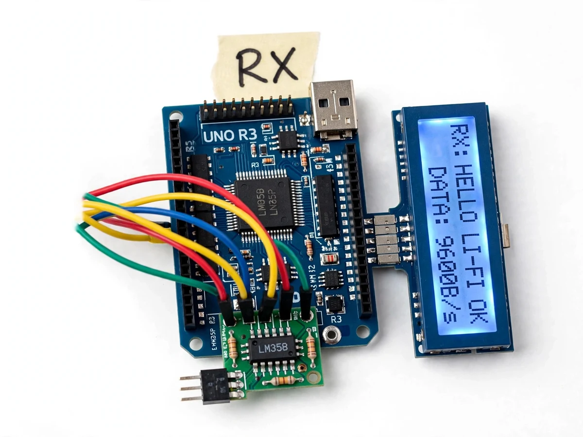
- The receiver Arduino samples the pulse stream, waits for the sync header, then decodes each byte back into a character.
- Decoded characters accumulate into the message string, which is printed to the 16x2 LCD; a checksum/frame check flags any corrupted block as an error rather than displaying it.
Tech stack:
- Arduino Nano · Arduino Uno
- LM358 op-amp (transimpedance amplifier)
- PIN photodiode (visible-light receiver)
- BC547 transistor LED driver
- 16x2 character LCD (I2C)
- Arduino IDE (C/C++ firmware)
- High-brightness white LED
| Parameter | Value |
|---|---|
| Communication medium | Visible light (free-space optical) |
| Transmitter controller | Arduino Nano (ATmega328P, 16 MHz) |
| Receiver controller | Arduino Uno (ATmega328P, 16 MHz) |
| Light source | High-brightness white LED, transistor-switched |
| Optical sensor | PIN photodiode (spectral response ~400–1100 nm, datasheet range) |
| Amplifier | LM358 transimpedance stage (slew rate 0.3 V/µs, datasheet) |
| Data rate | 9600 bps (design target; configurable in firmware) |
| Range | Up to ~1 m indoor line-of-sight (design target; depends on ambient light and alignment) |
| Display | 16×2 character LCD with I2C backpack |
| Power | 5 V USB or 9 V battery (transmitter), 5 V USB (receiver) |
| Encoding | 8-bit ASCII with sync header and frame validation |
Project features
- [Visible-light text transmission] Type a text string at the transmitter; it travels as modulated LED light pulses through free space and appears on the receiver's 16x2 LCD — a genuine wireless link with no radio involved.
- [Kilohertz LED switching driver] An Arduino Nano drives a high-brightness white LED through a BC547 transistor stage, switching the LED at kilohertz rates so the flicker is invisible to the eye while carrying data.
- [Photodiode receiver front end] A PIN photodiode feeds an LM358-based transimpedance amplifier that converts picoamp-scale photocurrents into clean voltage swings the receiver Arduino can sample.
- [Frame synchronization] Each transmission starts with a header/sync pattern so the receiver can lock onto the incoming bit stream and reject stray light flicker.
- [Error indication] The receiver validates incoming frames and flags corrupted transmissions on the LCD instead of displaying garbage, demonstrating real link-reliability thinking.
- [Configurable baud rate] Data rate is adjustable in firmware (design target 9600 bps), so students can demonstrate the trade-off between speed and link robustness.
- [Ambient-light thresholding] The comparator reference is adjustable, letting the receiver be tuned against room lighting conditions — a genuine receiver-design exercise.
- [LCD live readout] The 16x2 display shows received text plus link status, so the demo is self-explanatory during evaluation.
What is included
- Working Li-Fi transmitter module (Nano + LED driver on breadboard/PCB)
- Working photodiode receiver module (Uno + LM358 front end + 16x2 LCD)
- Complete firmware source code (transmitter + receiver, commented)
- Circuit and wiring documentation
- Component list with exact part numbers
- Setup and calibration instructions (threshold tuning procedure)
- Project report PDF (background, theory, methodology, results)
- PPT presentation for final review
- Viva Q&A preparation document (modulation, photodiode physics, noise, link budget)
Limitations & prerequisites
- Requires clear line-of-sight: the beam must hit the photodiode — an obstruction breaks the link instantly, like all free-space optical links.
- Indoor range is a design target of approximately 1 m; bright ambient sunlight or strong tube-light flicker can overwhelm the receiver at longer distances.
- Data rate tops out at a design target of 9600 bps with this analog front end — the LM358's 0.3 V/µs slew rate (datasheet) limits how fast clean pulses can be sliced.
- The link is point-to-point only: one transmitter to one receiver, no addressing or multi-node networking in the base build.
- High-speed alignment matters: the LED and photodiode must face each other within a narrow cone for reliable decoding.
- This is an academic demonstration prototype, not a certified communication device — range and rate figures are design targets, not measured guarantees.
Frequently Asked Questions
Is this project suitable for a final-year project?
Yes — for Electronics, Telecommunication and related programs. It demonstrates visible-light communication, modulation and demodulation, op-amp signal conditioning, and embedded firmware in one working build, and it maps cleanly to communication-theory and optoelectronics coursework.
Which controller and sensor are used?
An Arduino Nano drives the LED transmitter and an Arduino Uno handles the receiver, which uses a PIN photodiode (400–1100 nm response) with an LM358 transimpedance amplifier — a real analog front end, not just a digital light sensor.
How fast can it send text?
The design target is 9600 bits per second, configurable in firmware. That is fast enough for sentences to appear on the LCD essentially as typed, and slow enough that the LM358 amplifier stage can slice the pulses cleanly.
Does it work in daylight or a bright room?
Bright ambient light is the main enemy of any optical receiver — the photodiode sees it as noise. The comparator threshold is adjustable to compensate, and the receiver's sync header rejects flicker, but direct sunlight on the sensor will degrade the link; indoor demonstration is the reliable setting.
What can be customized?
Realistic options: longer message buffers, multiple receiver nodes, adding encryption of the transmitted text, a PC-side transmitter GUI, or upgrading the front end for higher data rates — quoted separately.
What will I receive with the project?
Both working hardware modules (transmitter and receiver), all firmware source code, wiring documentation, component list, calibration instructions, the project report PDF, PPT, and a viva Q&A document. Suitable for B.E./B.Tech final-year projects in Electronics, Telecommunication and IoT.
Components & software requirements
- Arduino Nano · Arduino Uno
- LM358 op-amp (transimpedance amplifier)
- PIN photodiode (visible-light receiver)
- BC547 transistor LED driver
- 16x2 character LCD (I2C)
- Arduino IDE (C/C++ firmware)
- High-brightness white LED
Delivery information
Built-to-order project. Delivery timeline is shared after order confirmation based on current queue.
Support terms
Complete documentation, setup guide, and viva preparation included. Support for setup and explanation provided.
Download free synopsis (PDF)
Enter your name and email — the synopsis PDF downloads immediately. We may send occasional project updates; no spam, unsubscribe anytime.