
More project photos (2)

The problem
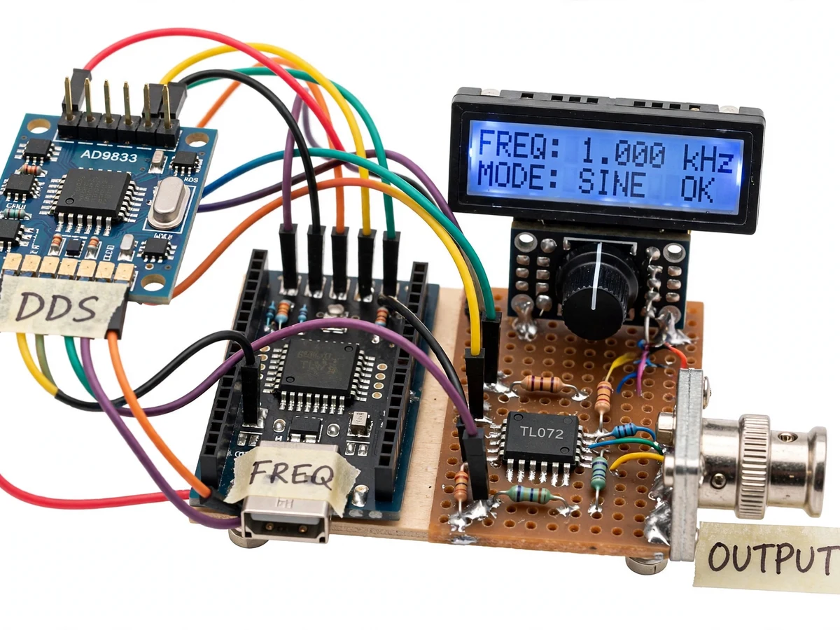
Every electronics lab needs a function generator, and commercial ones are expensive enough that students often share one unit across a bench — or do without. The core of the instrument is direct digital synthesis: a phase accumulator and lookup table that turn a digital word into a precise, stable waveform, a technique that replaced analog oscillators in real test equipment decades ago. This project puts that technique in the student's hands: an AD9833 DDS module generates sine, square and triangle waves under Arduino control, a rotary encoder and LCD provide the front panel, and an op-amp stage adds the amplitude and DC-offset control a bare DDS module lacks. The student ends up with a working bench instrument they calibrated themselves, and a report that explains DDS from first principles.
How it works
- The student selects waveform type and dials the frequency with the rotary encoder; the LCD shows the exact setting digit by digit.
- The Arduino programs the AD9833 over SPI with the computed frequency word; the DDS chip's internal phase accumulator and lookup table produce the waveform.
- The raw DDS output passes through the op-amp conditioning stage, where amplitude and DC offset are set by the front-panel controls.
- Frequency presets stored in EEPROM are recalled with the encoder push-button for repeat measurements.
- In sweep mode the firmware steps the DDS frequency across the configured span while the student observes the circuit under test.
- During calibration the student compares output frequency and amplitude against a reference instrument and trims the firmware constants.
Tech stack:
- Arduino Nano (ATmega328P)
- AD9833 DDS waveform generator module
- 16x2 LCD + rotary encoder (front panel)
- TL072 / LM358 op-amp output stage
- SPI interfacing
- Arduino IDE (C/C++ firmware)
| Parameter | Value |
|---|---|
| Waveforms | Sine, square, triangle (DDS-generated) |
| Frequency range | 0.1 Hz to 12.5 MHz (AD9833 design range) |
| Frequency resolution | Approximately 0.1 Hz steps at low range (design target) |
| Output amplitude | Approximately 0–5 Vpp adjustable (expected) |
| DC offset | Approximately ±2.5 V adjustable (expected) |
| Output impedance | Approximately 50 Ω series (design target) |
| Display | 16x2 LCD: frequency, waveform, amplitude, mode |
| Presets | 5 user presets in EEPROM (design target) |
| Supply | 5 V USB / 9 V adapter |
Project features
- [DDS waveform core] AD9833 module generates sine, square and triangle waves via direct digital synthesis — the same principle used in commercial generators.
- [0.1 Hz to 12.5 MHz range] Frequency settable in fine steps through the full DDS range of the AD9833 (design target), covering audio, ultrasonic and RF-test use cases.
- [Rotary-encoder front panel] A rotary encoder with push-select and a 16x2 LCD replicate a real instrument's user interface: digit-by-digit frequency editing.
- [Amplitude and offset control] Op-amp output stage provides adjustable amplitude and DC offset, so waveforms are centered or shifted as the experiment demands.
- [Frequency presets] Stores a small set of user presets in EEPROM for one-touch recall of commonly used test frequencies.
- [Sweep mode] Firmware sweeps the frequency across a configured span for filter and amplifier response checks.
- [Buyer-run calibration] Step-by-step procedure aligns the LCD frequency and output amplitude against a reference, with results recorded in the report.
What is included
- Working function-generator prototype (DDS module, Arduino, front panel, output stage)
- Arduino firmware with menu, presets and sweep mode
- Wiring diagram and assembly documentation
- Calibration procedure against a reference instrument
- Project report PDF (DDS theory, SPI, op-amp conditioning, calibration results template)
- PPT presentation for final review
- Viva Q&A preparation document
Limitations & prerequisites
- The AD9833 is a 10-bit DDS: waveform purity is good but not laboratory-grade — expect visible quantization steps on the fastest edges at the top of the range.
- Square-wave rise time is limited by the op-amp stage bandwidth; the 12.5 MHz top end applies to sine output.
- Output amplitude accuracy is approximately ±5% after the buyer-run calibration; it is a student-built instrument, not a calibrated reference.
- Sweep mode is manual-observation only — there is no built-in frequency-response plotting.
- The single supply design limits the maximum undistorted output swing.
Frequently Asked Questions
What is direct digital synthesis?
A digital phase accumulator advances by a frequency word each clock tick, and a lookup table converts the phase to amplitude samples. Changing the frequency word changes the output frequency instantly and precisely — no analog tuning drift.
How accurate is the frequency?
It follows the AD9833's crystal reference (typically ±20 ppm per the module datasheet), far more stable than an analog oscillator — the buyer-run calibration confirms it against a reference.
Can it drive real lab experiments?
Yes — filter response checks, amplifier gain tests, ultrasonic transducer drive and microcontroller clock injection are all within its range, which is why the amplitude and offset stage is included.
Why add an op-amp stage to a DDS module?
The bare AD9833 outputs a small fixed-amplitude signal centered on a DC bias. The op-amp stage gives the adjustable amplitude and DC offset a real instrument needs.
What does the sweep mode do?
It steps the output frequency across a configured span so you can watch a filter or amplifier's response change — the observation is manual, recorded by the student.
Is this project suitable for a final-year project?
Yes — for Electronics and Communication, Electrical and Instrumentation programs. It demonstrates DDS theory, SPI interfacing, analog conditioning and instrument calibration in one build. Suitable for B.E./B.Tech final-year projects in Electronics and Communication, Electrical and Instrumentation.
Components & software requirements
- Arduino Nano (ATmega328P)
- AD9833 DDS waveform generator module
- 16x2 LCD + rotary encoder (front panel)
- TL072 / LM358 op-amp output stage
- SPI interfacing
- Arduino IDE (C/C++ firmware)
Delivery information
Built-to-order project. Delivery timeline is shared after order confirmation based on current queue.
Support terms
Complete documentation, setup guide, and viva preparation included. Support for setup and explanation provided.