
More project photos (2)
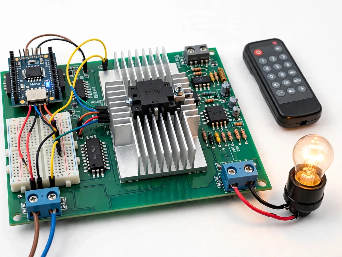
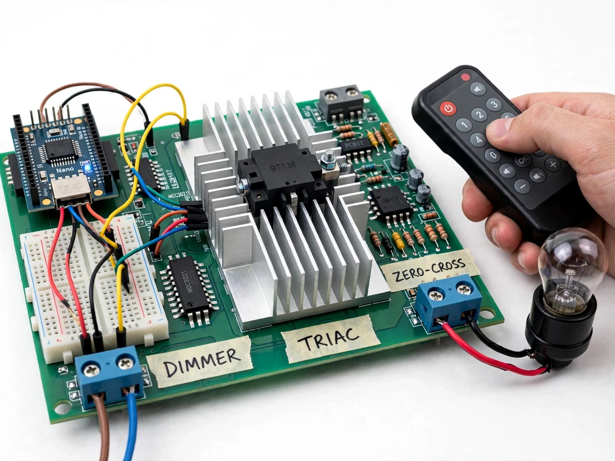
The problem
The Triac-Based AC Light Dimmer with Zero-Crossing Detection and Remote Control changes lamp brightness by switching mains power on for only part of each half-cycle, rather than wasting energy as heat in a series resistor. Ordinary wall dimmers hide this mechanism inside a sealed unit, so students rarely see the timing relationship between the mains waveform, the zero-crossing pulse, and the triac firing instant. A laboratory bench that only switches a lamp on and off also misses the point, because it never shows how conduction angle sets average power. The result is a gap between textbook phase-control diagrams and a working circuit that a student can measure, adjust, and explain. The dimmer built here closes that gap with a timed firing circuit, an isolated gate drive, and a remote control that makes each brightness step visible on a real lamp load.
This is a built-to-order hardware project: the assembled dimmer prototype, firmware, circuit and wiring documentation, and the complete documentation kit are prepared fresh for you.
Concept
A triac stays off until its gate receives a trigger pulse, then conducts for the remainder of that mains half-cycle until the load current falls below its holding current near the next zero crossing. Delaying the trigger pulse therefore shortens conduction and dims the lamp, while an early pulse lengthens conduction and brightens it. The zero-crossing detector gives the controller a fresh timing reference at every half-cycle, so the delay is measured from a known point instead of drifting against the mains waveform. Builder note from the actual build: the first prototype flickered at low brightness because the zero-crossing sense wiring ran alongside the gate-drive wiring and picked up switching noise, and the fix was to route the sense and gate-drive wiring apart and keep the low-voltage and mains sections physically separated on the board. First-principles line: firing angle and conduction angle are complementary within one half-cycle, so a longer firing delay always means a shorter conduction slice and therefore lower average power to the lamp.
230 V AC mains input through a fuse and terminals.
Follow the working sequence
How it works
Mains power enters the dimmer through a fuse and terminal blocks, while a zero-crossing detector watches the mains waveform and pulses each time the voltage passes through zero. An Arduino Nano measures the delay from that pulse, waits for the selected firing delay, and then sends a short gate pulse through the MOC3021 optoisolated driver to the BT136 triac. The triac then conducts for the rest of that half-cycle and switches off naturally near the next zero crossing, so the lamp receives only the chosen slice of each half-cycle and the average power falls as the delay grows. Changing the delay changes the conduction slice and therefore the brightness, and the infrared remote changes the delay value the controller uses for the next cycle. A snubber damps switching transients, a heatsink carries heat from the triac, and the enclosure stays closed throughout, so the whole chain from mains input to lamp output runs as one timed, isolated, and protected sequence.
- Mains supply at 230 V AC and 50 Hz enters through a fuse and clearly labelled terminal blocks into the enclosed mains section of the board.
- The zero-crossing detector, built from a bridge rectifier and a PC817 optocoupler, produces a pulse each time the mains waveform crosses zero volts.
- The Arduino Nano receives that pulse as an interrupt and starts a timer for the firing delay selected by the remote control.
- When the timer expires, the controller drives the MOC3021 optoisolator, which passes a gate pulse to the BT136 triac by light with no direct electrical connection to the controller.
- The triac conducts for the remainder of that half-cycle, delivering power to the incandescent lamp load, then turns off naturally as the load current falls near the next zero crossing.
- The remote receiver decodes each infrared command and updates the firing delay, the on-off state, or the preset brightness level for the next half-cycle.
- A resistor-capacitor snubber across the triac damps voltage transients at switching, while the heatsink carries heat away from the triac during sustained operation.
Tech stack:
- Arduino Nano
- Arduino IDE · C firmware
- BT136 triac · heatsink
- MOC3021 optoisolated triac driver
- PC817 zero-crossing detector
- Infrared remote · TSOP receiver
- Incandescent lamp load
- Enclosed mains terminal block · fuse
| Parameter | Value |
|---|---|
| Mains supply | 230 V AC (design target, Indian mains) |
| Mains frequency | 50 Hz (design target) |
| Triac | BT136-600E (datasheet value) |
| Triac repetitive peak off-state voltage | 600 V (datasheet value) |
| Triac RMS on-state current | 4 A (datasheet value) |
| Triac non-repetitive surge current | 25 A for 20 ms (datasheet value) |
| Triac driver | MOC3021 (datasheet value) |
| Driver peak blocking voltage | 400 V (datasheet value) |
| Driver isolation voltage | 5300 V RMS (datasheet value) |
| Driver LED trigger current | 15 mA maximum (datasheet value) |
| Zero-crossing detector isolation | 5000 V RMS for PC817 (datasheet value) |
| Demo lamp load | 100 W incandescent lamp (design target) |
| Control | Infrared remote (design target) |
| Half-cycle period at 50 Hz | 10 ms (datasheet-derived value) |
| Controller supply | 5 V DC regulated (design target) |
| Enclosure | Closed enclosure before power-on (design requirement) |
Project features
The Triac-Based AC Light Dimmer with Zero-Crossing Detection and Remote Control offers phase-angle dimming, mains-synchronised timing, optoisolated gate drive, and infrared remote control in a single bench prototype. Phase-angle dimming gives smooth brightness steps instead of a simple on-off switch, while zero-crossing detection anchors every firing delay to the mains waveform so brightness stays steady from cycle to cycle. Optoisolation keeps the low-voltage controller electrically separate from the mains switching stage, and the remote lets a demonstrator change brightness without touching the board. Snubber protection and a fused, enclosed mains section complete the build, so the timing, the power stage, and the safety separation are all visible and testable in one prototype that a reviewer can follow step by step. A reviewer can therefore trace one remote press through timing, isolation, and conduction to the lamp in a single demonstration.
- [Phase-angle dimming] The controller delays the triac gate pulse by a controlled amount after each zero crossing, so the lamp receives a shorter or longer conduction slice and visibly changes brightness in steps.
- [Zero-crossing detection] A bridge-rectifier and optocoupler detector produces a timing pulse at each mains half-cycle, giving the firmware a stable reference from which every firing delay is measured.
- [Optoisolated triac drive] The MOC3021 driver couples the gate signal by light, not by a copper connection, so the Arduino Nano side stays electrically separated from the mains side of the circuit.
- [Infrared remote control] A handheld infrared remote with an IR receiver sets brightness up and down, switches the lamp on and off, and selects preset brightness levels without touching the live board.
- [On-board brightness indication] Indicator LEDs and the lamp itself show the selected level during a demonstration, so a reviewer can follow each remote command to its visible effect on the load.
- [Snubber and fuse protection] A resistor-capacitor snubber across the triac damps switching transients, and a mains fuse in series with the load limits fault current in the prototype.
- [Enclosed mains section] The mains wiring, triac, and terminal blocks are housed in an enclosure with the board closed before power is applied, so no live conductor is exposed during normal demonstration.
Optional customization: a potentiometer for manual brightness control can be added on request, and a second lamp channel can be developed as a separate extension; neither is part of the base single-channel build. Future scope: power measurement display, fan-speed control mode, and wireless control are possible extensions and are not included in the base build.
What is included
- Assembled triac dimmer prototype with Arduino Nano, triac and heatsink, optoisolated driver, zero-crossing detector, infrared receiver, and enclosed mains section
- Infrared remote control and incandescent lamp load for demonstration
- Firmware source code with firing-delay and remote-decoding logic
- Circuit diagram, wiring documentation, and component list
- Project report PDF covering phase control, zero-crossing timing, isolation, and safety procedure
- Abstract PDF matching the project page
- PPT presentation for final review
- Demonstration guidance and a safe power-on checklist
Limitations & prerequisites
- This is a teaching and demonstration build, not a certified product, and it must never be installed as permanent household wiring or sold as a consumer dimmer.
- Mains work is hazardous: assembly, inspection, and any wiring change must be done only with the supply disconnected and under qualified supervision, and the enclosure must be closed before power is applied.
- The demo load is a resistive incandescent lamp (design target); inductive loads such as fans and motors, LED lamps, and CFL lamps behave differently and are out of scope for the base build.
- Phase-angle dimming chops the mains waveform, so it can introduce flicker at very low brightness and electrical noise that a commercial dimmer would filter more thoroughly.
- Brightness steps are set by firing delay, not by a calibrated light meter, so no lux or efficiency figure is claimed for the built unit.
- The infrared remote needs a clear line of sight to the receiver, and strong ambient infrared light can interfere with commands.
- The triac and heatsink must be checked for temperature during extended demonstration, and the unit must be switched off and unplugged if the heatsink becomes excessively hot or any smell, smoke, or damage appears.
Timeline
- Week 1 (expected): circuit design, component procurement, and board assembly under supervision.
- Week 2 (expected): firmware development for zero-crossing timing, firing delay, and remote decoding.
- Week 3 (expected): enclosed bench testing with the lamp load, documentation, report, and presentation preparation.
Support
- Demonstration guidance and a safe power-on checklist are included with the build.
- Wiring and firmware questions during the review period are answered with reference to the supplied circuit diagram and code.
- Any mains-side modification after delivery must be reviewed before power is applied, and the unit must not be opened while powered.
Frequently Asked Questions
How does triac phase-angle dimming actually work?
Triac phase-angle dimming works by switching the triac on part-way through each mains half-cycle, so the lamp receives only the remaining slice of that half-cycle and therefore less average power than a fully-on lamp. A longer delay leaves a shorter conduction slice and a dimmer lamp, while a shorter delay leaves a longer slice and a brighter lamp. The triac then switches off naturally near the next zero crossing, ready for the next timed pulse.
Why is zero-crossing detection needed?
Zero-crossing detection is needed because the firing delay must be measured from a known point on the mains waveform, otherwise the delay drifts against the cycle and brightness flickers or jumps unpredictably. The detector pulses at each zero crossing, and the controller times its gate pulse from that pulse, so the same setting lands at the same point in every cycle. Without that reference, a fixed timer alone could not stay synchronised with the mains.
Is the low-voltage controller safe from the mains side?
The controller is electrically separated from the mains side by optocouplers, but the complete board is still a mains-powered prototype and must always be treated as hazardous equipment. The MOC3021 driver and the PC817 detector couple signals by light, with datasheet isolation ratings stated in the specifications, and the mains section is enclosed during operation. Separation reduces risk, but it does not make an open or modified board safe to touch.
What kind of lamp can it dim?
It is designed for a resistive incandescent lamp load, which is the demo load supplied with the base build, because such lamps respond predictably to a chopped waveform. The filament smooths the power steps between cycles, so brightness changes look steady rather than flickering with each switching event. LED lamps, CFL lamps, fans, and motors need different drive and filtering, so they are out of scope unless a variant is specifically developed.
Can the dimmer be controlled without the remote?
Yes, manual control can be added as an optional customization, but the base build is remote-controlled by design and ships with the infrared remote as its only supplied control. A potentiometer input can be developed on request to set brightness by hand, since the firmware already treats brightness as a single delay value. Changing the control source would not change the power stage, so the same triac and timing circuit could be kept.
Is this project suitable for a final-year project?
Yes, it fits Electrical, Electronics, and E&TC final-year work because it combines power electronics, microcontroller timing, and mains safety in one demonstrable build that a reviewer can test live. Students can explain phase control, zero-crossing timing, optoisolation, and snubber design from the same prototype, using the lamp as visible evidence for every setting. The enclosed mains section also gives a concrete safety discussion for the review, rather than a purely theoretical circuit.
Components & software requirements
- Arduino Nano
- Arduino IDE · C firmware
- BT136 triac · heatsink
- MOC3021 optoisolated triac driver
- PC817 zero-crossing detector
- Infrared remote · TSOP receiver
- Incandescent lamp load
- Enclosed mains terminal block · fuse
Delivery information
Built-to-order project. Delivery timeline is shared after order confirmation based on current queue.
Support terms
Complete documentation, setup guide, and viva preparation included. Support for setup and explanation provided.
Download free synopsis (PDF)
Enter your name and WhatsApp number — the synopsis PDF downloads immediately. We may send occasional project updates on WhatsApp; no spam.