
More project photos (2)
The problem
In many homes the switch board sits behind furniture, beside a doorway, or in a room that is already dark, so switching a fan or a light off means walking over, feeling for the switch, and walking back. For an elderly person, a person with limited mobility, or anyone carrying something in both hands, that short walk is a daily nuisance, and lights and fans are often left running simply because switching them off takes effort. Phone-based home automation answers that nuisance with a new one: an app to install, a device to pair, a network to keep alive, and a phone that must be charged and nearby. The RF Remote-Controlled Home Appliance Switch Board with 4 Channels takes a simpler route: a small handheld remote with 4 buttons, one button for each of 4 mains appliances, works from across a room with no phone, no app and no network in between.
This is a built-to-order hardware project: the switch-board prototype, Arduino Nano firmware, report, abstract and presentation material are built fresh for each order.
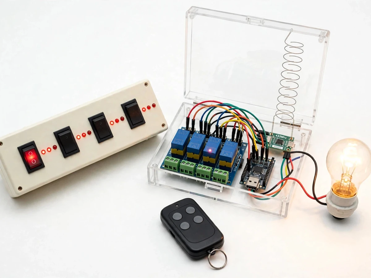
The RF Remote-Controlled Home Appliance Switch Board with 4 Channels solves the walk-to-the-switch problem without asking the household to adopt a phone app, a hub, or a wireless network. Pressing a button on the handheld remote sends a coded radio burst on the 433 MHz band; a receiver beside the switch board hands the code to an Arduino Nano, and the Nano toggles the relay for that channel, switching a bulb, a fan, a table lamp, or a charger point on or off from across a room. Each channel carries its own LED indicator, so the state of every appliance is visible at a glance on the board itself, and each channel also carries a manual override switch, so an appliance can still be switched by hand when the remote is misplaced or its battery runs flat. Mains wiring stays inside an enclosed board with low-voltage control wiring kept apart, and the design documents its safety limits plainly.
Presses one of the 4 buttons on the remote.
Follow the working sequence
How it works
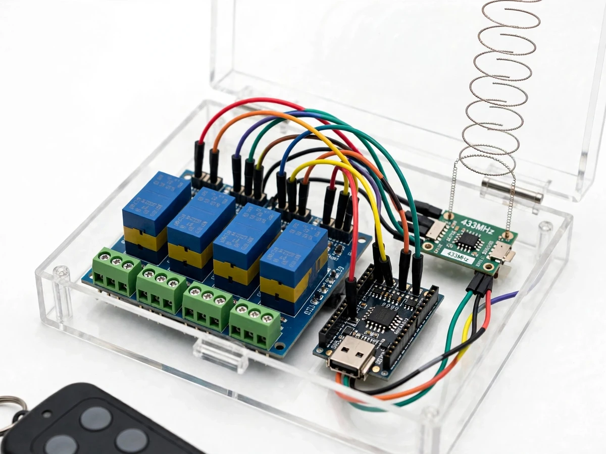
The RF Remote-Controlled Home Appliance Switch Board with 4 Channels works as a short chain from button press to appliance. Pressing a button makes the handheld remote transmit a short coded burst on the 433 MHz band using amplitude shift keying, in which the carrier is switched on and off to carry binary data. A receiver module beside the board with a vertical coiled antenna picks up the burst and passes the recovered code to an Arduino Nano. Nano firmware compares the received address code with its stored code, ignores codes that do not match, and toggles the digital output for the matching channel. That output drives the corresponding relay on the 4-channel relay board, the relay contacts close or open, the appliance switches on or off, and the channel LED follows the new state. A manual rocker wired across each relay contact can force its appliance on by hand; returning it hands control back to the relay.
- The user presses a button on the handheld remote, and the remote transmits a short coded burst on the 433 MHz band containing a fixed address code and the pressed button code.
- The receiver module picks up the burst through its coiled antenna, recovers the code, and passes it to the Arduino Nano for checking.
- Nano firmware compares the received address code with its stored code, ignores any code that does not match, and toggles the digital output assigned to the matching channel.
- The toggled output drives the matching relay on the 4-channel relay board: the relay coil energises or releases, the contacts close or open, the appliance switches on or off, and the channel LED follows the new state.
- Pressing the same button again repeats the chain and toggles the channel back, so each button works as an on-off toggle for its own appliance.
- If the remote is unavailable, flipping a channel rocker to its override position forces that appliance on directly; flipping the rocker back returns the appliance to relay control, noting that the remote cannot switch an appliance off while its override rocker is on.
- After a power cut, the firmware restarts every channel in the OFF state, and the user re-selects the wanted channels from the remote or the rockers.
- The range check finishes the setup: each channel is operated from each room in turn, dropout points are noted, and the antenna is repositioned vertically and clear of metal before the board is treated as ready.
Builder note from the build: during bench testing the relays chattered when the receiver antenna lay flat against the relay board and the relay coils shared an unregulated feed with the logic, so the antenna was remounted vertically and clear of metal and mains wiring, and the relay board was given its own regulated 5 V feed with the logic ground kept common; the chatter stopped and every button press then produced a single clean relay action. The same note records the pairing check used before delivery: each button is pressed in turn with its load connected, and the channel number, LED state and load state are ticked off together, so a crossed wire between two channels cannot hide behind a working remote.
Tech stack:
- Arduino Nano controller board
- 433 MHz ASK transmitter in the handheld remote
- 433 MHz ASK receiver module with coiled antenna
- 4-channel relay board with opto-isolated inputs
- Manual override rocker switches with LED indicators
- 5 V DC regulated power supply for logic and relays
- Arduino IDE firmware (C/C++ sketch)
- Insulated enclosure with separated low-voltage and mains sections
| Parameter | Value |
|---|---|
| Control channels | 4 channels |
| Radio link | 433 MHz ASK link (datasheet band) |
| Controller | Arduino Nano board · 5 V logic (datasheet value) |
| Relay board | 4-channel relay board · 10 A contacts at 250 V AC (datasheet value) |
| Logic and relay supply | 5 V DC regulated supply (design value) |
| Handheld remote | 4-button remote · 433 MHz transmitter · 12 V battery (typical value) |
| Demonstration loads | 4 mains loads: bulb · fan · table lamp · charger point |
| Channel indicators | 4 LED indicators · 1 LED per channel |
| Manual override | 4 rocker switches · 1 switch per channel |
| Operating range | 30 m open-air range (design target) · reduced by walls and obstacles |
Project features
The RF Remote-Controlled Home Appliance Switch Board with 4 Channels is built around 4 capabilities that matter in daily use. Radio switching comes first: a handheld remote with 4 buttons controls 4 separate mains appliances from across a room, with each button mapped to exactly 1 channel, so there is no menu to navigate and no screen to unlock. Per-channel LED indication comes second: a small LED beside each switch shows whether its channel is on, giving instant feedback without walking to the appliance. Manual override comes third: a rocker switch for each channel powers its appliance by hand when the remote is out of reach, flat, or lost. No-phone operation comes fourth: control needs no app, no pairing step, no account and no network, so the board keeps working during an internet outage and can be used by anyone who can press a button.
- [4-channel RF switching] Each of the 4 remote buttons toggles 1 mains appliance independently — a bulb, a fan, a table lamp or a charger point — over a coded 433 MHz radio link. Included in the base build.
- [Per-channel LED indicators] A dedicated LED beside each switch shows whether its relay channel is on, so the state of every appliance can be read from the board at a glance. Included in the base build.
- [Manual override per channel] A rocker switch wired across each relay contact forces its appliance on by hand; flipping the rocker back returns control to the relay. Included in the base build.
- [Toggle action with a safe power-on state] Pressing a button toggles its channel on or off, and after a power cut all channels restart in the OFF state so no appliance restarts unexpectedly. Included in the base build.
- [No phone, app or network needed] Control travels over a one-way 433 MHz link from a dedicated remote, so there is no pairing step, no account and no dependence on an internet connection. Included in the base build.
- [Enclosed mains section with separated wiring] Mains conductors stay inside a closed, insulated enclosure, with low-voltage control wiring routed apart from the mains side. Included in the base build.
- [Independent channel control] Toggling any channel leaves the other channels untouched, so switching a lamp on never disturbs a running fan or a charging device. Included in the base build.
Optional and future scope (not in the base build): additional relay channels, a second remote, timer-based switching, fan speed control, and energy metering. These can be developed on request and are not claimed as included.
What is included
- Working prototype: enclosed switch board with 4-channel relay board, Arduino Nano, 433 MHz receiver and handheld remote
- Arduino Nano firmware with address-code check, toggle logic and safe power-on state
- Circuit diagram, wiring documentation and component list with relay and module ratings and mains separation notes
- Project report (background, design, working, safety notes, limitations)
- Project abstract PDF (10 sections, matching the page)
- PPT presentation for final review
- Setup and range-test guide with pairing check and antenna placement notes
- Viva Q&A preparation document (radio link, relay switching, mains safety)
Limitations & prerequisites
- Mains safety: the prototype is a demonstration unit, not a certified household installation; mains wiring and any fixed installation must be done or checked by a qualified person, and the enclosure must stay closed during operation.
- Range: the 30 m figure is an open-air design target; walls, metal enclosures and other 433 MHz devices reduce usable range, and no measured in-house range is claimed — use the included walk test.
- One-way link: the remote sends and the board never replies, so switching is confirmed by the channel LED and the appliance itself, not by any feedback on the remote.
- Override holds: while a manual override rocker is on, the remote cannot switch that appliance off until the rocker is flipped back.
- Power-on reset: all channels restart in the OFF state after an outage, so previous channel states are not remembered.
- Load limits: relay contacts are rated 10 A at 250 V AC (datasheet value) for resistive loads, so motor or compressor loads need a derating check against the datasheet, and fan switching in the base build is on-off only with no speed control.
- Link security: the address code prevents casual cross-talk, but the link is unencrypted and is not access security — a transmitter using the same code could toggle a channel.
Frequently Asked Questions
Is this project suitable for a final-year project?
Yes, it suits B.E. and B.Tech programmes in Electrical Engineering, because it combines radio communication, microcontroller firmware, relay switching and mains safety in one working prototype that reviewers can test button by button. It also gives the student a complete story to explain: how a coded radio burst becomes a relay action, why the mains section is enclosed, and where the design limits lie. The build covers circuit design, firmware logic, antenna placement and a safe testing procedure, and the report documents each stage with ratings taken from datasheets rather than measured claims.
How is this different from Bluetooth or phone-controlled home automation?
It differs because control comes from a dedicated handheld remote over a 433 MHz radio link, with no phone, no app, no pairing step, no account and no network standing between the user and the switch board. That makes it usable by anyone who can press a button, and it keeps working when the internet is down or the phone is charging in another room. The trade-off is deliberate: there is no scheduling, no dimming, no voice control and no status shown on a phone, because the base build trades those features for simple, direct control that needs no setup.
What happens if the remote is lost or the radio link stops working?
Nothing is stranded, because each channel has a manual override rocker on the board itself, so every appliance can still be switched by hand while a replacement remote is arranged. A replacement remote works once it transmits the same address code as the receiver expects, which is checked button by button against each channel, its LED and its load before the board is handed over. The override rocker holds its appliance on until it is flipped back, so the household is never locked out of a light or a fan by a flat remote battery.
Is it safe to switch mains appliances with a student-built prototype?
It is safe to demonstrate only under clear limits: mains conductors stay inside a closed, insulated enclosure with low-voltage wiring routed apart, and any mains wiring or fixed installation is done or checked by a qualified person. The board is a demonstration prototype, not a certified household installation, and it must never be opened or rewired while connected to mains supply. Low-voltage behaviour is tested first with the enclosure open and mains disconnected, and load testing uses the demonstration loads named on the page, with each load checked against the relay contact rating before it is connected.
Can more channels or different appliances be added later?
Yes, extra channels can be added by fitting a relay board with more channels, adding matching buttons to the remote, and extending the firmware mapping, provided spare digital outputs and supply current remain available. Different appliances can be substituted only after checking each load against the relay contact rating, because a load above the rating must never be connected to the board. Timer switching, fan speed control and energy metering are realistic extensions, developed on request rather than included in the base build.
What range can I expect inside a real house?
Expect less than the 30 m open-air design target, because walls, metal enclosures, furniture and other 433 MHz devices all shorten the usable range, and no measured in-house range is claimed for the prototype. The honest way to know the range in a particular house is the included walk test: operate each channel from each room in turn and note where commands stop responding reliably. Keeping the receiver antenna vertical, clear of metal and away from mains wiring gives the most reliable result, and the antenna position is rechecked first whenever a channel starts responding inconsistently.
Components & software requirements
- Arduino Nano controller board
- 433 MHz ASK transmitter in the handheld remote
- 433 MHz ASK receiver module with coiled antenna
- 4-channel relay board with opto-isolated inputs
- Manual override rocker switches with LED indicators
- 5 V DC regulated power supply for logic and relays
- Arduino IDE firmware (C/C++ sketch)
- Insulated enclosure with separated low-voltage and mains sections
Delivery information
Built-to-order project. Delivery timeline is shared after order confirmation based on current queue.
Support terms
Complete documentation, setup guide, and viva preparation included. Support for setup and explanation provided.
Download free synopsis (PDF)
Enter your name and WhatsApp number — the synopsis PDF downloads immediately. We may send occasional project updates on WhatsApp; no spam.