
More project photos (2)
The problem
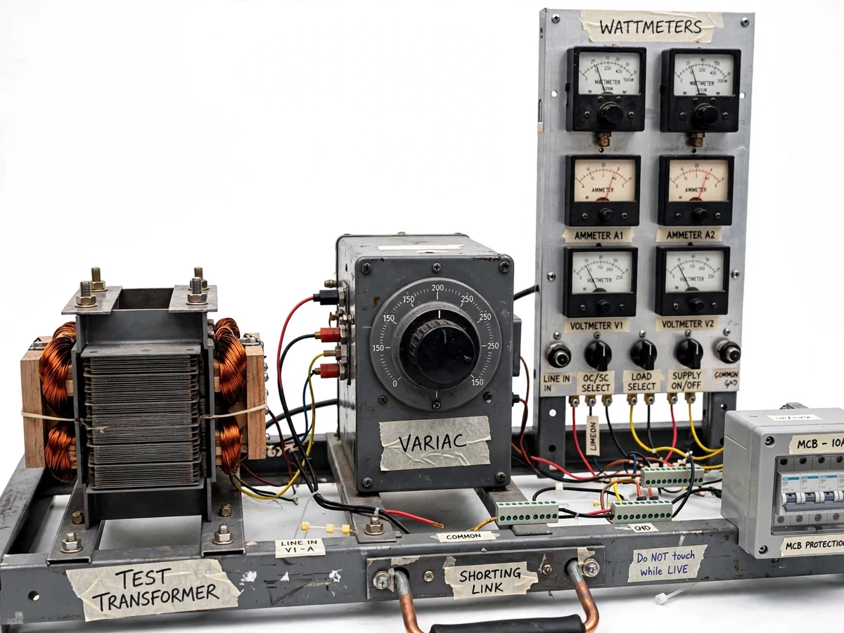
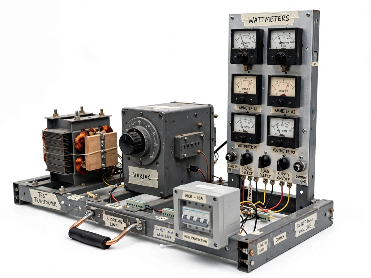
No transformer is ever fully described by its nameplate: the equivalent circuit parameters, the efficiency at various loads and the voltage regulation all come from two elegant experiments — the open-circuit test and the short-circuit test. The OC test, run at rated voltage with the secondary open, draws only the no-load current, so the wattmeter reads essentially the core loss and gives the shunt branch of the equivalent circuit. The SC test, run at reduced voltage with the secondary shorted, draws rated current at low voltage, so the wattmeter reads the full-load copper loss and gives the series impedance. From these two tests the student computes efficiency at any load and power factor, and the regulation — the complete performance picture. This project builds that bench properly: a test transformer, variac, wattmeters and meters wired through selector switching, with the standard two-wattmeter-free single-phase procedure, so every parameter in the report is measured by the student.
How it works
- The test transformer is connected per the OC-test wiring diagram: variac-fed rated voltage to the LV winding, HV winding left open.
- Voltage is raised slowly to rated value; no-load current, voltage and power are recorded — the wattmeter reads the core loss.
- Connections are changed to the SC-test diagram: the LV is shorted with the shorting link and reduced voltage is applied to the HV.
- Voltage is raised only until rated current flows; voltage, current and power are recorded — the wattmeter reads the full-load copper loss.
- Core-loss and copper-loss figures give the shunt and series branches of the equivalent circuit on the computation sheets.
- Efficiency at chosen loads and power factors, and the voltage regulation, are computed from the equivalent circuit for the report.
Tech stack:
- Single-phase test transformer (1 kVA class)
- Variable autotransformer (variac)
- Wattmeters (suitable ranges for OC and SC)
- AC ammeters and voltmeters
- Heavy shorting link with insulated handle
- MCB protection and zero-start interlock
- Selector switching and marked terminals
- Calculation sheets and graph formats
| Parameter | Value |
|---|---|
| Test transformer | Approximately 1 kVA, 230/115 V single-phase (design target) |
| Variac | Approximately 0–270 V, 4 A (design target) |
| OC test | At rated voltage, HV open (procedure) |
| SC test | At reduced voltage for rated current, LV shorted (procedure) |
| Parameters found | Ro, Xo (from OC); Rk, Xk (from SC) — student-computed |
| Derived results | Efficiency vs load, regulation (student-computed) |
| Overall size | Approximately 700 × 500 × 600 mm (design target) |
Project features
- [OC test configuration] Rated-voltage supply through the variac to the LV winding with the HV open — wattmeter, ammeter and voltmeter wired for the no-load test.
- [SC test configuration] Reduced-voltage supply to the HV winding with the LV shorted through a heavy shorting link — meters wired for the short-circuit test.
- [Variac control] A continuously variable autotransformer gives the fine voltage control both tests need, with zero-start interlock wiring.
- [Proper instrument set] Wattmeters of the correct range for each test plus ammeters and voltmeters, with the connection diagrams showing exact terminal wiring.
- [Equivalent-circuit computation sheets] Ready sheets take the student from test readings to Ro, Xo, Rk, Xk and the referred equivalent circuit.
- [Efficiency and regulation sheets] Calculation formats for efficiency at multiple loads and power factors, and for percentage regulation, from the test data.
- [Safety interlocks] MCB protection, variac zero-start interlock and a shorting link with insulated handle, with the operating sequence card.
What is included
- Fully assembled OC/SC test bench with transformer and variac
- Wattmeters, ammeters and voltmeters fitted and wired
- OC and SC wiring diagrams with terminal schedule
- Equivalent-circuit, efficiency and regulation calculation sheets
- Safe operating sequence card (variac zero-start procedure)
- Project report PDF (transformer test theory, bench design, test methodology)
- PPT presentation for final review
- Viva Q&A preparation document (why OC on LV side, why SC on HV side, separation of losses, Sumpner's test as extension)
Limitations & prerequisites
- All parameters, efficiency and regulation figures are computed from the student's own test readings — no values are claimed as measured before the build.
- The bench uses one test transformer rating; the procedure is written so the student can repeat it on any available lab transformer.
- Wattmeter readings need the correct range and connection for each test — the diagrams mark this explicitly, and wrong-range readings are a listed viva pitfall.
- The SC test must be run at reduced voltage only; the interlock and procedure card enforce the variac zero-start sequence.
- Single-phase only in the base build; three-phase OC/SC testing is listed as future scope.
Frequently Asked Questions
Why is the OC test done on the LV side?
At rated voltage the no-load current is small, so it is convenient and safer to apply rated voltage to the LV winding. The SC test is then done on the HV side because rated current is reached at a low, safe voltage there.
What does each wattmeter actually read?
In the OC test the no-load copper loss is negligible, so the wattmeter reads essentially the core (iron) loss. In the SC test the core loss is negligible at reduced voltage, so it reads the full-load copper loss.
How are efficiency and regulation found without a load test?
From the two losses: efficiency at any load and power factor follows from output/(output + core loss + load² × copper loss), and regulation from the series impedance — the standard indirect method, worked in the sheets.
What is Sumpner's test, mentioned in the viva kit?
The back-to-back test for two identical transformers that gives temperature-rise data the OC/SC tests cannot. It is covered as theory and future scope since it needs two identical units.
Is this project suitable for a final-year project?
Yes — for Electrical programs. The OC/SC tests are core electrical-machines experiments, and the bench makes them a complete measurement-to-results project. Suitable for B.E./B.Tech final-year projects in Electrical Engineering.
Components & software requirements
- Single-phase test transformer (1 kVA class)
- Variable autotransformer (variac)
- Wattmeters (suitable ranges for OC and SC)
- AC ammeters and voltmeters
- Heavy shorting link with insulated handle
- MCB protection and zero-start interlock
- Selector switching and marked terminals
- Calculation sheets and graph formats
Delivery information
Built-to-order project. Delivery timeline is shared after order confirmation based on current queue.
Support terms
Complete documentation, setup guide, and viva preparation included. Support for setup and explanation provided.