
More project photos (3)


The problem
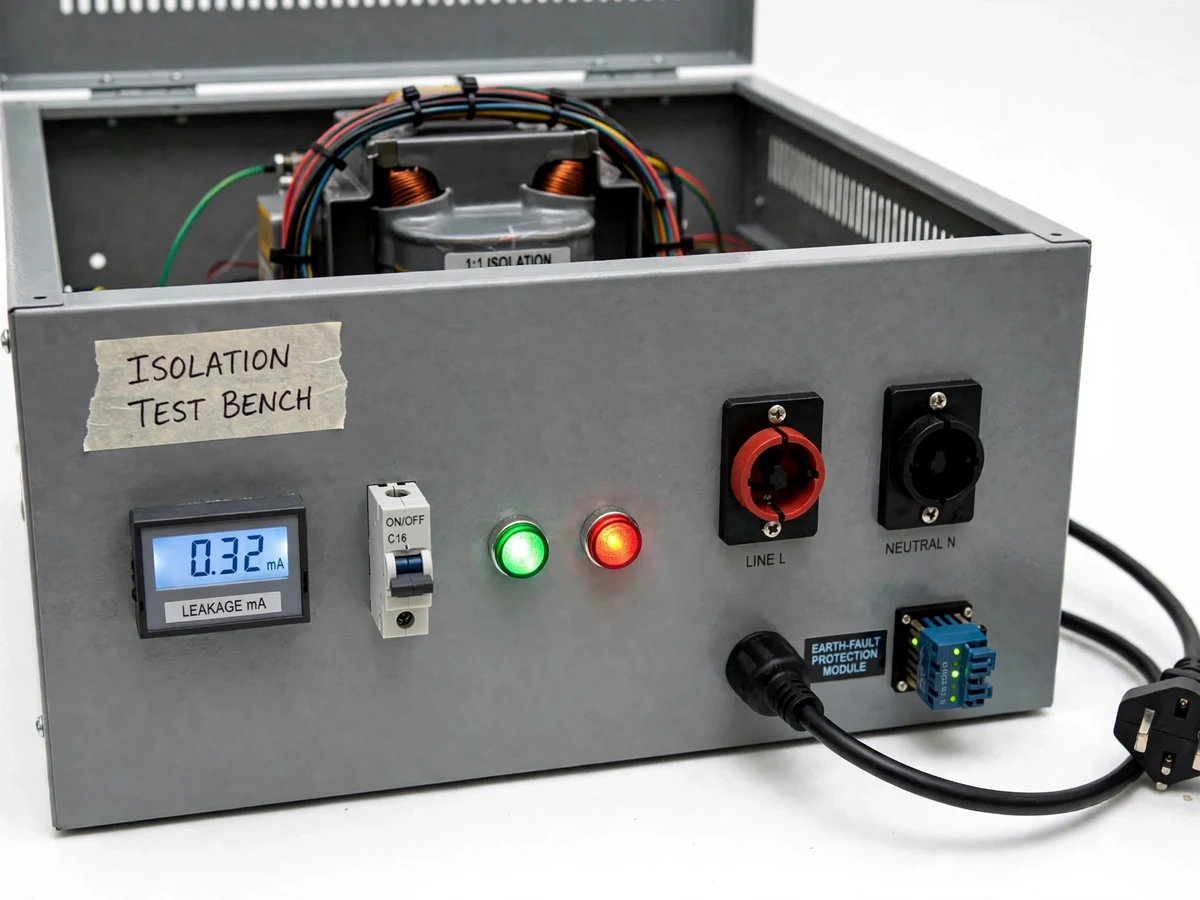
An isolation transformer test bench gives an electronics lab a safe way to power and test mains-powered equipment that is under repair, under development, or being demonstrated. In a wall socket, one side of the supply is tied to earth, so touching a part while standing on an earthed floor can complete a circuit through the body, and clipping an oscilloscope ground lead to the wrong point can short the circuit under test. This bench breaks that path. A 1:1 isolation transformer passes 230 V across at the same voltage while its secondary floats free of earth, so there is no return path through the bench earth for a single fault to exploit. The bench adds a leakage-current meter, an MCB, and earth-fault protection that cut the supply when stray current appears, plus shrouded test sockets and indicator lamps that make the bench state visible at a glance. It is a lab tool for supervised testing, not a certified product.
Mains at 230 V AC and 50 Hz enters through the fused inlet and the 16 A MCB.
Follow the working sequence
How it works
The isolation transformer test bench works end to end as a chain of five stages: mains input, galvanic isolation, floating test socket, continuous measurement, and protection. Mains at 230 V and 50 Hz enters through a fused inlet and the MCB, which guards against overcurrent. It then feeds the primary of a 1:1 isolation transformer, whose secondary delivers the same 230 V but floats free of earth because the two windings share only a magnetic field, not a wire. The floating secondary feeds shrouded test sockets where the equipment under test is plugged in, so a single accidental contact cannot complete a circuit back through earth. While the equipment runs, a leakage-current sensing circuit measures stray current flowing to earth and shows it on a digital panel meter in milliamps, with green and red lamps showing healthy and fault states. If leakage crosses the design trip level, the earth-fault protection trips and disconnects the test socket.
- Mains at 230 V AC and 50 Hz enters the bench through a fused inlet and the 16 A MCB.
- The MCB feeds the primary winding of the 1:1 isolation transformer.
- The floating secondary delivers 230 V AC at 50 Hz to the shrouded LINE and NEUTRAL test sockets, with no earth reference.
- The equipment under test is plugged into the test sockets and powered from the floating supply.
- The leakage-current sensing circuit continuously measures stray current to earth and displays it in milliamps on the panel meter.
- If leakage crosses the 30 mA trip level (design target) or an overcurrent occurs, the protection module and MCB disconnect the test socket and the red lamp shows the fault state.
Builder note: the secondary must stay floating. If the bench earths the secondary neutral — the single most common wiring mistake on the test-socket side — the isolation is gone and the bench behaves like an ordinary wall socket, silently. The build checks this with a continuity test between the secondary and earth before first power-up: it must read open. Galvanic isolation breaks the earth-return path, so an oscilloscope ground clip no longer shorts the circuit under test.
Tech stack:
- 1:1 isolation transformer
- MCB · earth-fault protection
- Leakage-current sensing
- Digital panel meter
- Shrouded test sockets
- Steel enclosure · ventilation
- Mains wiring · earthing practice
- Multimeter · insulation tester (verification)
| Parameter | Value |
|---|---|
| Input supply | 230 V AC, 50 Hz (standard Indian mains) |
| Transformer | 1:1 ratio, 250 VA (design value) |
| Output voltage | 230 V AC floating secondary, 50 Hz |
| Output current | Approximately 1.1 A maximum (design value) |
| MCB | 16 A, C-curve (datasheet value) |
| Leakage trip level | 30 mA (design target) |
| Leakage display | Digital panel meter, 0–30 mA range (design value) |
| Test sockets | 2 shrouded sockets, LINE and NEUTRAL |
| Indicator lamps | 2 lamps (green power, red fault), 230 V |
| Enclosure | Grounded steel enclosure with ventilation slots |
| Frequency | 50 Hz |
Project features
Four systems in the bench work together: a floating 230 V supply, visible leakage monitoring, fast fault disconnection, and a bench that is safe to operate by hand. The 1:1 isolation transformer is the core, removing the earth reference from the test supply so oscilloscope ground clips and accidental contact no longer create a short or a shock path. A digital panel meter continuously displays leakage current in milliamps, so a developing fault is seen before it becomes dangerous. Earth-fault protection and a 16 A MCB cut the supply when leakage or overcurrent crosses the trip level, and the trip is indicated by a red lamp. Shrouded test sockets, a ventilated steel enclosure, and clear labelling keep live parts out of reach during normal use. Together these make the bench a practical teaching tool for transformer isolation, earthing, and protection.
- [1:1 isolation transformer] A 250 VA (design value) transformer with equal primary and secondary windings delivers 230 V at 50 Hz while keeping the secondary floating, so the test supply has no earth reference.
- [Floating shrouded test sockets] Two shrouded 4 mm sockets (LINE and NEUTRAL) accept the equipment under test, with recessed contacts that keep fingers clear of live metal during normal use.
- [Leakage-current display] A digital panel meter continuously shows leakage current in milliamps, so stray current through a faulty device is visible while the test is running.
- [Earth-fault protection trip] A protection module disconnects the test socket when leakage crosses the 30 mA trip level (design target), with a red lamp showing the tripped state until it is reset.
- [MCB overcurrent protection] A 16 A C-curve MCB (datasheet value) guards the bench and the equipment under test against overload and short circuit on the mains side.
- [Status indicator lamps] Green and red panel lamps show power-on and fault states at a glance, so the bench state is obvious from across the lab bench.
- [Ventilated steel enclosure] A grounded steel enclosure with ventilation slots houses the transformer and wiring, keeping live parts enclosed and heat from building up inside.
Optional customization (not in the base build): data logging of leakage readings to a laptop over USB, for recording fault behaviour during a demonstration.
Future scope (not in the base build): automatic test-sequence logging with a microcontroller, and a remote trip-status indicator for the lab supervisor's desk.
What is included
- Working isolation transformer test bench, assembled, wired and tested
- 1:1 isolation transformer, MCB, earth-fault protection module and leakage-current meter fitted in the enclosure
- Wiring diagram and component list with ratings
- Test report covering continuity, isolation and trip checks carried out before dispatch
- Project report PDF (background, transformer theory, protection coordination, methodology, test results)
- PPT presentation for final review
- Viva Q&A preparation document (isolation, earthing, leakage current, protection devices)
Limitations & prerequisites
- This bench works with 230 V mains: it must be built and tested under supervision, and it is a lab bench, not a certified product.
- The bench provides a floating supply and monitors leakage; it does not measure insulation resistance, which needs a separate high-voltage tester.
- The 30 mA trip level is a design target, not a certified protection rating, and no medical-grade leakage limit is claimed for this non-medical bench.
- The 250 VA rating (design value) limits the load to approximately 1.1 A; larger equipment needs a higher-rated transformer, quoted separately.
- The bench protects against single-fault earth leakage; touching both floating conductors at once is still dangerous, so live terminals must never be touched during a test.
- Leakage readings depend on the condition of the equipment under test; a healthy device can still show small stray current, which the report explains.
- The bench is a prototype for academic use; it is not a substitute for certified lab safety equipment or a licensed electrician's test gear.
Timeline
- Build and testing take approximately 3–4 weeks from order confirmation, including the continuity, isolation and trip checks.
- Delivery timeline is confirmed on WhatsApp with the quotation, before the build starts.
Support
- 30 days of WhatsApp and email support after delivery for wiring, testing and demonstration questions.
- Guidance on safe test procedure and on repeating the isolation and trip checks in the college lab.
Frequently Asked Questions
Is this project suitable for a final-year project?
Yes, for Electrical Engineering and Electronics & Telecommunication students. It demonstrates transformer isolation, earthing, leakage current, MCB and earth-fault protection, and safe mains testing in one working bench, with a clear, documented test procedure and measurable checks for the review. The build is a good fit where the guide wants a practical electrical-safety project rather than a software-only topic.
How does the isolation transformer make testing safer?
It breaks the earth-return path. The secondary floats free of earth, so touching one live conductor while standing on an earthed floor cannot complete a circuit through the body, and an oscilloscope ground clip no longer shorts the circuit under test. The transformer passes 230 V across at the same voltage, so the equipment under test runs normally while the shock path through earth is removed. Protection still matters: touching both floating conductors at once remains dangerous.
What is the most common wiring mistake on the test-socket side?
Earthing the secondary neutral is the mistake. If the floating secondary is tied to earth anywhere on the test-socket side, the isolation is silently lost, the bench behaves like an ordinary wall socket, and the whole point of the build is defeated. That is the single most common wiring mistake on this bench, and it is invisible until it is tested. The build guards against this with a continuity check between the secondary and earth before first power-up, which must read open, and the wiring diagram marks the floating secondary clearly so the mistake is easy to spot during the review.
Does this bench measure insulation resistance?
No. This bench provides a floating 230 V supply and monitors leakage current while equipment under test is running, but it never applies a high test voltage to measure insulation resistance, which is a different test done with a separate insulation-resistance tester. That measurement belongs to a different project. If the college needs insulation-resistance measurement, it is quoted as a separate instrument, not as part of this bench.
Can the trip level or the transformer rating be changed?
Yes, both are configurable at order time. The 30 mA trip level is a design target and can be set to a different value on request, and the 250 VA transformer can be replaced with a higher-rated unit for larger loads, with the MCB rating matched to it. Any change is confirmed in the quotation with the scope, price and delivery timeline before the build starts, so the review documentation matches the bench that is delivered.
What will I receive with the project?
The assembled and tested bench, the wiring diagram and component list, a test report covering the continuity, isolation and trip checks, the project report PDF, a PPT for the final review, and a viva Q&A document. Delivery is built-to-order against a quotation confirmed on WhatsApp, and 30 days of support after delivery cover wiring, testing and demonstration questions.
Components & software requirements
- 1:1 isolation transformer
- MCB · earth-fault protection
- Leakage-current sensing
- Digital panel meter
- Shrouded test sockets
- Steel enclosure · ventilation
- Mains wiring · earthing practice
- Multimeter · insulation tester (verification)
Delivery information
Built-to-order project. Delivery timeline is shared after order confirmation based on current queue.
Support terms
Complete documentation, setup guide, and viva preparation included. Support for setup and explanation provided.
Download free synopsis (PDF)
Enter your name and WhatsApp number — the synopsis PDF downloads immediately. We may send occasional project updates on WhatsApp; no spam.