
More project photos (3)
The problem
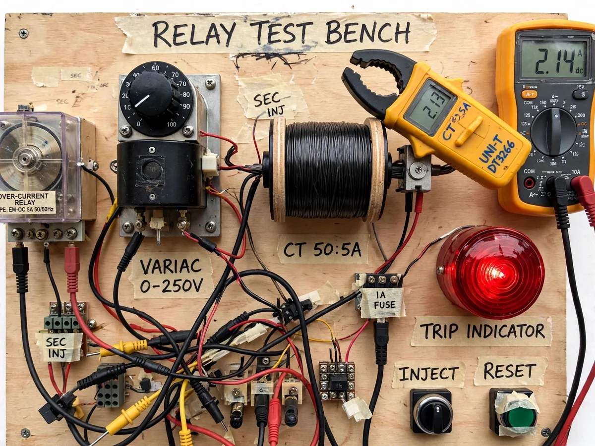
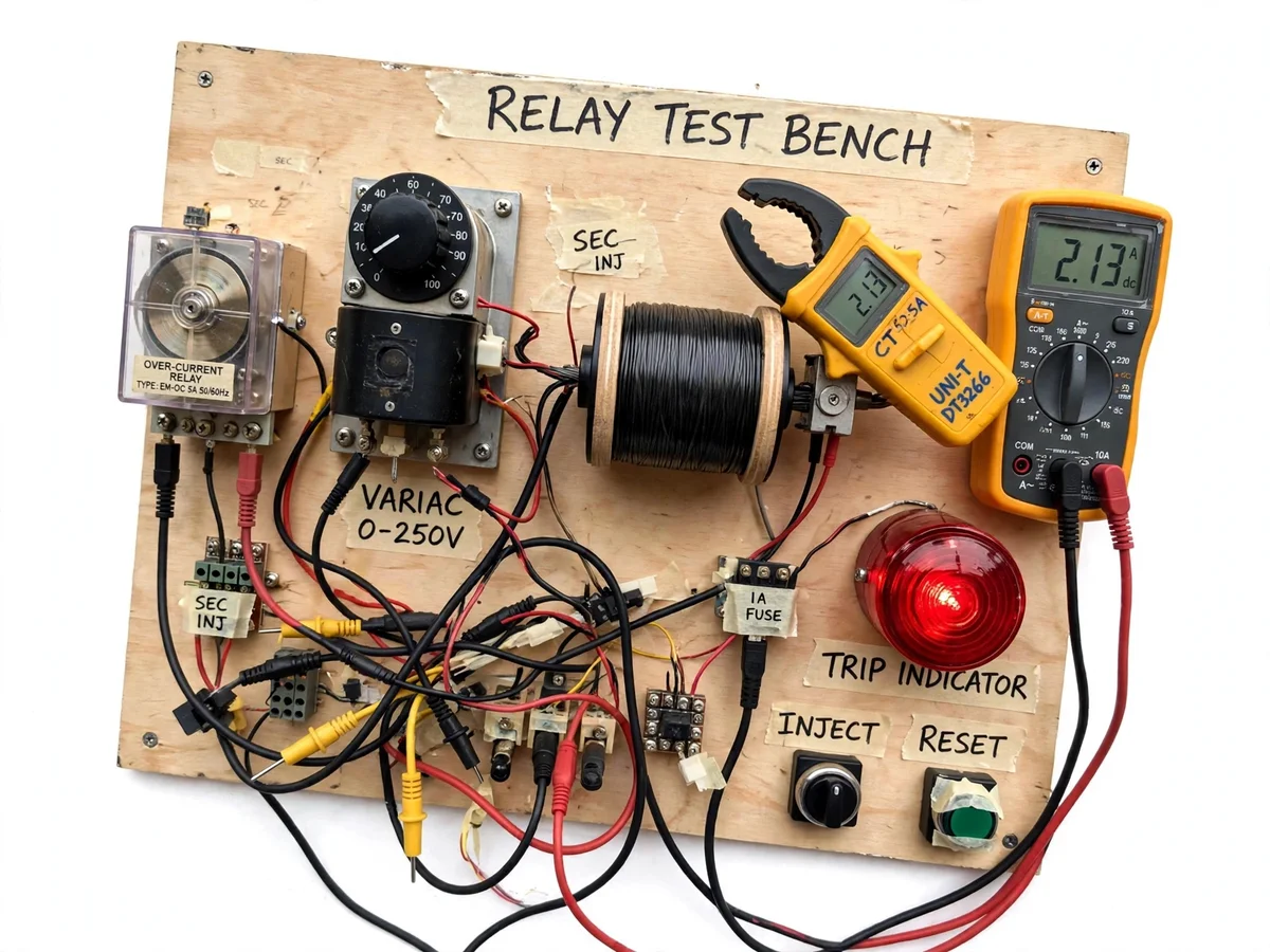
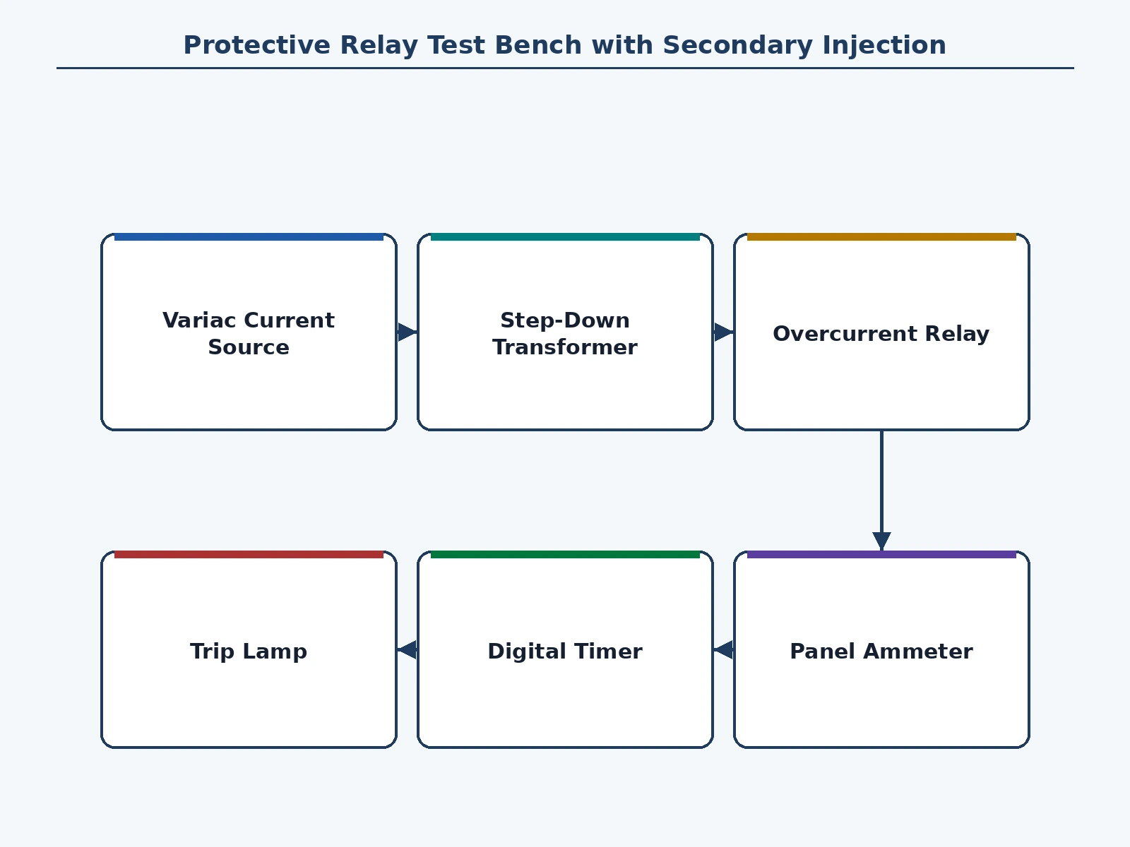
Protective relays are the silent guardians of the power system, but a relay whose pickup has drifted or whose timing is off is worse than no relay at all — it either trips healthy feeders or sits idle through a fault. That is why relays are tested periodically, and the standard field method is secondary injection: instead of driving huge primary fault currents, the technician injects a controlled current into the relay's current-transformer secondary terminals and checks pickup, timing and instantaneous operation against the relay's characteristic. This project builds exactly that as a bench. A variac feeding a step-down transformer gives a smoothly variable AC test current up to the design range; the relay under test is an electromagnetic induction-disc overcurrent relay with plug-setting and time-setting adjustments; a digital timer and ammeter record each test; and a trip lamp marks the relay's operation. The student sets the plug, injects 2x, 5x and 10x multiples, times each trip, and plots the IDMT curve — the same test sheet a protection engineer fills in the field.
Bench energized from the mains through an isolation transformer for safety.
Follow the working sequence
How it works
- The bench is energized from the mains through an isolation transformer, and the variac is set to zero with the injection circuit open.
- The relay's plug-setting multiplier is selected on its tap links, and the time-setting multiplier is set on the dial.
- The injection leads are connected to the relay's current terminals — the CT-secondary terminals the relay would see in service.
- The variac is raised slowly while watching the ammeter; the current at which the disc starts to move is recorded as the pickup current.
- The current is set to 2 times the pickup value, the timer is armed, and injection starts — the timer stops when the trip lamp lights.
- The test is repeated at 5x and 10x pickup, and at a second time-setting, and the recorded times are plotted as the relay's time-current characteristic.
- The instantaneous element, if fitted, is checked by injecting a high multiple and confirming near-instant trip.
Tech stack:
- Protection relay theory
- IDMT time-current characteristics
- Secondary injection method
- Variac current control
- AC ammeter instrumentation
- Trip timing measurement
- PSM and TSM settings
- Electrical safety practices
| Parameter | Value |
|---|---|
| Injection current | 0–10 A AC, adjustable (design) |
| Current source | Variac 0–250 V feeding a step-down transformer (typical) |
| Relay under test | Electromagnetic induction-disc overcurrent relay, 5 A nominal (typical) |
| Timer resolution | 0.01 s (design target) |
| Plug-setting taps | 50–175% in steps (typical for the relay class) |
| Time-setting multiplier | 0.1–1.0 dial (typical for the relay class) |
| Supply | 230 V AC mains via isolation transformer (design) |
| Trip indication | Panel lamp from relay output contact (design) |
Project features
- [Variable current source] A variac feeding a step-down transformer provides smoothly adjustable AC test current, the heart of the secondary-injection method.
- [Electromagnetic overcurrent relay] An induction-disc overcurrent relay with plug-setting multiplier and time-setting multiplier adjustments is the unit under test.
- [Digital timer] A panel timer with 0.01 s resolution (design target) captures trip times for the time-current characteristic.
- [Panel ammeter] A digital ammeter shows the injected current, so pickup and multiples of setting are set precisely.
- [Trip indication] A trip lamp wired from the relay's output contact marks the exact moment of operation for timing.
- [PSM/TSM adjustment] Plug taps and the time dial are exposed and adjustable, so the student tests how each setting shifts the characteristic.
- [Test worksheet] A procedure sheet guides pickup measurement, timing at 2x/5x/10x, and plotting the IDMT curve.
What is included
- Bench panel with variac, step-down transformer, timer, ammeter and trip lamp
- Electromagnetic overcurrent relay under test with PSM/TSM adjustments
- Injection leads and terminal connections
- Wiring and schematic diagram of the injection circuit
- Test procedure and IDMT plotting worksheet
- Project report PDF (background, secondary injection theory, test results)
- PPT presentation for final review
- Viva Q&A preparation document (pickup, IDMT, PSM/TSM, injection vs primary)
Limitations & prerequisites
- This is secondary injection only — it does not test CT primary circuits, CT saturation, or wiring polarity.
- One relay is tested at a time; multi-relay coordination studies need repeated runs.
- Electromagnetic disc timing has mechanical scatter, so recorded times are indicative — the report presents the student's own readings honestly.
- Injection is limited to the design range of 10 A; primary injection needs a separate high-current source, noted as future scope.
- The bench works at low voltage through isolation, but the variac connects to mains — the supplied safety procedure must be followed.
Frequently Asked Questions
What is secondary injection testing?
Testing a protective relay by injecting current into its CT-secondary terminals instead of driving real primary fault current. It verifies the relay's own pickup, timing and trip output — which is what periodic maintenance actually checks — using a safe, controllable source.
How is it different from primary injection?
Primary injection drives current through the actual CT primary to test the whole chain: CT, wiring and relay together. It needs a high-current source and is done at commissioning. Secondary injection tests the relay alone and is the routine field method — which is what this bench implements.
What are PSM and TSM?
The plug-setting multiplier sets the current pickup as a multiple of the relay's nominal current; the time-setting multiplier shifts the whole time-current curve up or down. Together they decide how much current trips the relay and how fast.
How is trip timing measured?
The injection current is switched on with the timer armed; the relay's output contact lights the trip lamp and stops the timer. The elapsed time is the relay's operating time at that current multiple.
Why do relays need periodic testing?
Contacts wear, springs weaken, dust and vibration shift settings — a relay that drifts can fail to clear a fault or trip a healthy feeder. Periodic injection testing catches the drift before a fault does.
Is this project suitable for a final-year project?
Yes — for Electrical Engineering programs. It teaches protection philosophy, relay characteristics and the actual field test method in one bench. Suitable for B.E./B.Tech final-year projects in Electrical Engineering.
Components & software requirements
- Protection relay theory
- IDMT time-current characteristics
- Secondary injection method
- Variac current control
- AC ammeter instrumentation
- Trip timing measurement
- PSM and TSM settings
- Electrical safety practices
Delivery information
Built-to-order project. Delivery timeline is shared after order confirmation based on current queue.
Support terms
Complete documentation, setup guide, and viva preparation included. Support for setup and explanation provided.
Download free synopsis (PDF)
Enter your name and WhatsApp number — the synopsis PDF downloads immediately. We may send occasional project updates on WhatsApp; no spam.