
More project photos (3)
The problem
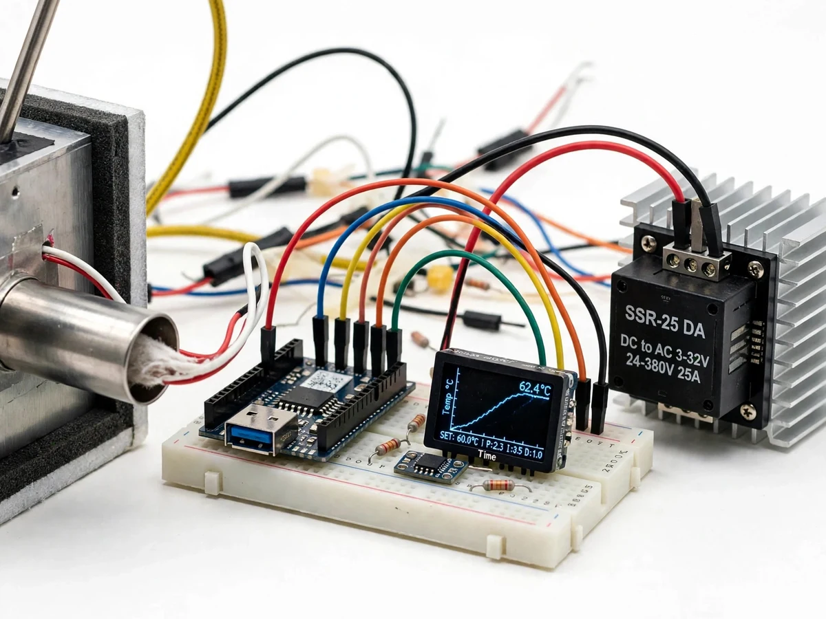
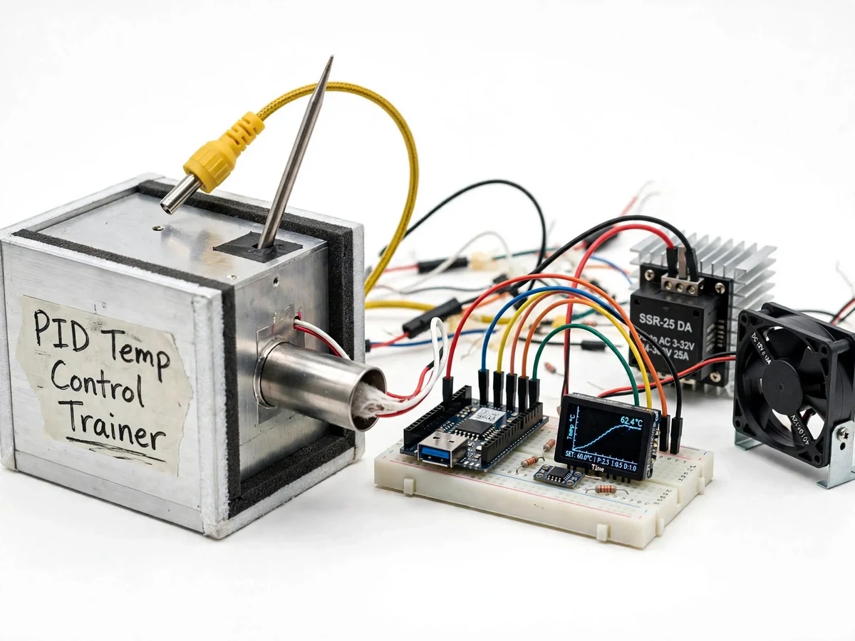
Temperature control loops run furnaces, ovens, 3D-printer hotends and injection-moulding machines, yet most students meet PID only as equations on a board. The gap between the math and a real loop is wide: on-off thermostats oscillate around the setpoint, proportional-only control leaves a steady offset, and tuning is treated as black magic. This trainer closes that gap with a physical thermal plant — an insulated chamber, a heater, a K-type thermocouple and an SSR-switched power stage driven by a microcontroller PID loop. Students measure the plant's slow dynamics, run the Ziegler-Nichols ultimate-gain experiment on real hardware, and compare P, PI and PID responses on the live trend display. A switched fan injects disturbances so the loop's rejection can be observed, and an autotune mode offers a second tuning route. It covers sensor limits, actuator saturation, thermal lag and the speed-versus-overshoot trade-off.
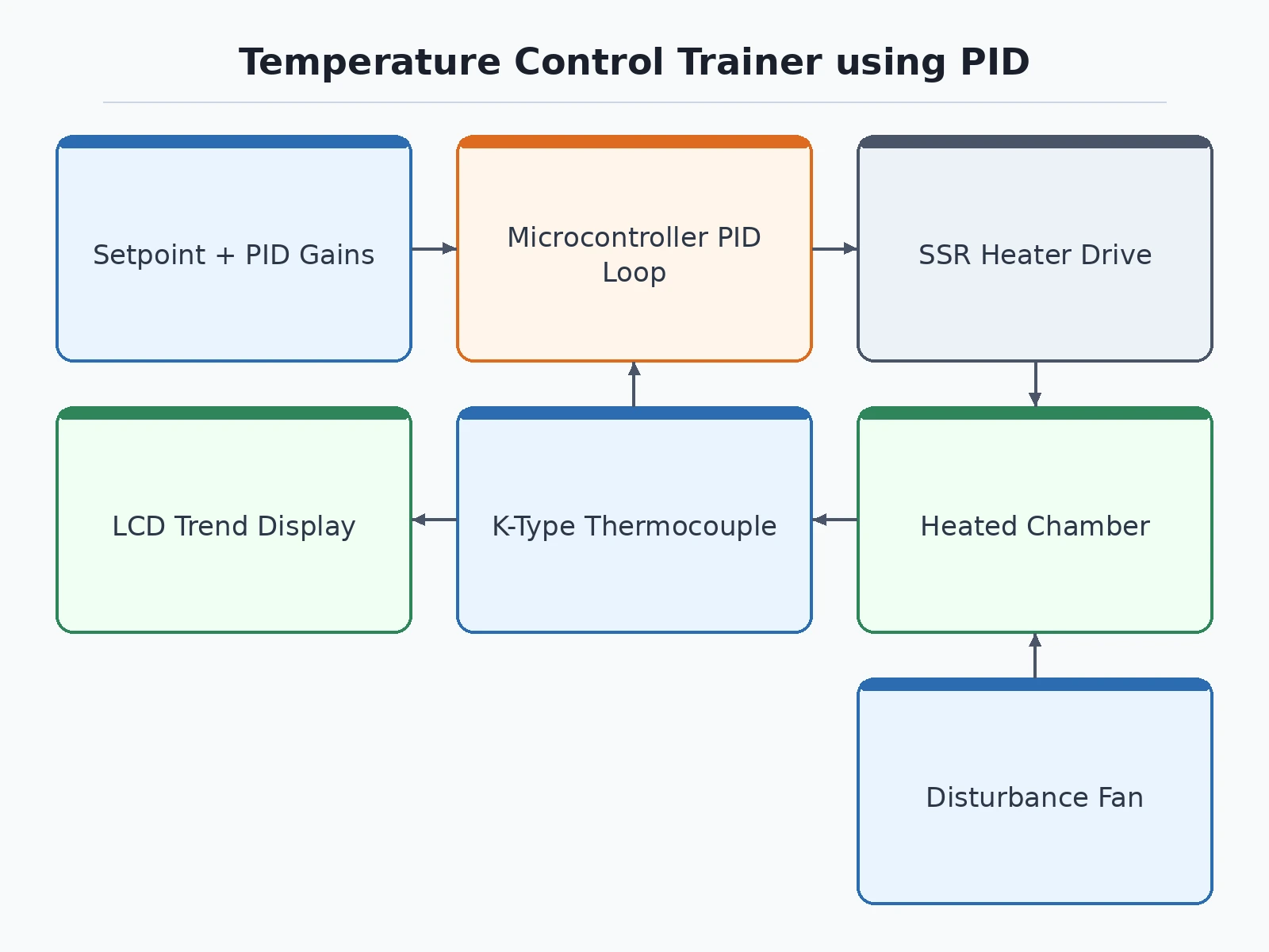
Sets the setpoint, tunes P/I/D gains and injects fan disturbances.
How it works
- The target temperature is set on the display buttons or over the serial console.
- The MAX31855 reads the K-type thermocouple once per second with cold-junction compensation.
- The PID routine computes the error (setpoint minus measured) and the P, I and D terms; the output is clamped to 0–100%.
- The output drives the SSR with slow PWM (2 s period typical), switching the heater; the zero-cross SSR keeps switching noise low.
- The trend display plots measured versus setpoint temperature; the fan can be switched on to inject a cooling disturbance.
- For tuning, manual mode runs the Ziegler-Nichols ultimate-gain experiment: Ku and Tu are recorded, gains computed from the Z-N table, entered, and the P, PI and PID responses compared side by side.
Tech stack:
- Arduino Nano / ESP32 running the PID loop, display and button input
- MAX31855 K-type thermocouple interface with cold-junction compensation
- 25 A zero-cross solid-state relay with heatsink for heater switching
- Cartridge or silicone-pad heater inside an insulated aluminum chamber
- 16x2 LCD or 0.96 inch OLED live-trend display
- Embedded C++ firmware with manual-tuning and relay-autotune modes
| Parameter | Value |
|---|---|
| Controller | Arduino Nano (ATmega328P) or ESP32 |
| Temperature sensor | K-type thermocouple + MAX31855 (±2°C typical, per datasheet) |
| Heater | 12/24 V cartridge or silicone-pad heater, 40–100 W class |
| Power switching | 25 A zero-cross SSR, optically isolated, heatsink fitted |
| Setpoint range | Ambient +10°C to ~180°C (heater and chamber dependent) |
| Control update | ~1 Hz PID loop with slow-PWM output (2 s period typical) |
| Tuning methods | Ziegler-Nichols ultimate-gain procedure + relay autotune mode |
| Display | LCD/OLED live trend of temperature vs setpoint |
| Disturbance source | Switched cooling fan directed across the chamber |
| Safety | Independent over-temperature cutout + thermal fuse |
| Power | 12/24 V DC supply for heater and logic |
Project features
- Closed-Loop PID Control: a microcontroller PID loop (approximately 1 Hz update) drives the heater through the SSR, tracking the setpoint with user-configurable P, I and D gains.
- Ziegler-Nichols Tuning Lab: the printed lab manual walks through the ultimate-gain experiment — raise Kp to sustained oscillation, record Ku and Tu, then compute P/PI/PID gains from the classic Z-N table.
- SSR Heater Drive: a 25 A zero-cross solid-state relay switches the heater with slow PWM, optically isolated from the 5 V logic side for safety.
- K-Type Thermocouple Sensing: MAX31855 cold-junction-compensated readout, ±2°C typical per the datasheet; DS18B20 or PT100 options for lower-temperature experiments.
- Disturbance Injection Fan: a switched fan blows across the chamber to simulate load disturbances, letting students watch the loop reject them in real time.
- Live Temperature Trend: an LCD/OLED display plots measured temperature against setpoint, so overshoot, offset and settling are visible without a PC.
- Safety Cutoff: an independent over-temperature cutout trips the heater relay above the configured limit regardless of firmware state, backed by a thermal fuse.
What is included
- Assembled thermal rig: insulated chamber, heater, thermocouple, SSR, controller board, display and enclosure
- Firmware source code (manual PID mode + relay-autotune mode + trend display)
- Wiring diagram and full component list with part numbers
- Ziegler-Nichols tuning lab manual with procedure and observation tables
- Project report PDF (theory, Z-N derivation, build, tuning-result format)
- PPT presentation and viva Q&A preparation document
- Setup and safety guide
Advantages
- Closed-loop PID control: a microcontroller PID loop (approximately 1 Hz update) drives the heater through the SSR, tracking the setpoint with user-configurable P, I and D gains.
- Ziegler-Nichols tuning lab: the printed lab manual walks through the ultimate-gain experiment — raise Kp to sustained oscillation, record Ku and Tu, then compute P/PI/PID gains from the classic Z-N table.
- SSR heater drive: a 25 A zero-cross solid-state relay switches the heater with slow PWM, optically isolated from the 5 V logic side for safety.
- K-type thermocouple sensing: MAX31855 cold-junction-compensated readout, ±2°C typical per the datasheet, with DS18B20 or PT100 options for lower-temperature experiments.
- Disturbance injection fan: a switched fan blows across the chamber to simulate load disturbances, letting students watch the loop reject them in real time, plus a live temperature trend on an LCD/OLED display plotting measured temperature against setpoint.
- Safety cutoff: an independent over-temperature cutout trips the heater relay above the configured limit regardless of firmware state, backed by a thermal fuse.
Disadvantages
- Thermal plants are slow: each tuning iteration needs tens of minutes to settle, so a full Ziegler-Nichols run is a multi-hour lab session rather than a quick demo.
- Control precision cannot beat the sensor: the K-type + MAX31855 chain is ±2°C typical per the datasheet, so regulation tighter than that cannot be honestly claimed — a PT100 option exists for finer experiments.
- Settling-time and overshoot figures are design targets from typical builds; your unit's numbers are measured during your build and documented in the report.
- The SSR needs its heatsink at sustained high duty cycles; running without it risks thermal damage to the relay.
- The heater runs from a low-voltage DC supply, but any mains-powered heater variant must be wired and first-powered under supervision — this is a heat-generating rig, not a toy.
Limitations & prerequisites
- Thermal plants are slow: each tuning iteration needs tens of minutes to settle, so a full Ziegler-Nichols run is a multi-hour lab session rather than a quick demo.
- Control precision cannot beat the sensor: the K-type + MAX31855 chain is ±2°C typical per the datasheet, so regulation tighter than that cannot be honestly claimed — a PT100 option exists for finer experiments.
- Settling-time and overshoot figures are design targets from typical builds; your unit's numbers are measured during your build and documented in the report.
- The SSR needs its heatsink at sustained high duty cycles; running without it risks thermal damage to the relay.
- The heater runs from a low-voltage DC supply, but any mains-powered heater variant must be wired and first-powered under supervision — this is a heat-generating rig, not a toy.
Frequently Asked Questions
Is this project suitable for a final-year project?
Yes — for Mechanical, Mechatronics, Instrumentation and E&TC programs. It demonstrates control theory (PID, Ziegler-Nichols), thermal-system dynamics, embedded C and isolated power switching, with strong viva material: why integral action removes offset, why derivative needs filtering on noisy sensors, and how Ku/Tu map to controller gains.
What is the Ziegler-Nichols method?
A classic empirical tuning procedure: increase the proportional gain until the loop oscillates steadily (the ultimate gain Ku, with period Tu), then set the P/PI/PID gains from the Z-N table. The lab manual walks through the whole experiment on the actual rig.
Which controller and sensor are used?
An Arduino Nano or ESP32 runs the loop; temperature comes from a K-type thermocouple via the MAX31855 (±2°C typical per datasheet). DS18B20 or PT100 sensing can be substituted for lower-temperature experiments.
Can the heater or chamber size be changed?
Yes, within limits — but any plant change needs the PID gains retuned, which is itself a worthwhile experiment; the manual covers the retuning procedure.
What will I receive with the project?
The assembled rig, firmware source, wiring diagram, component list, Ziegler-Nichols lab manual, project report, PPT, viva Q&A and a setup/safety guide. Suitable for B.E./B.Tech final-year projects in Mechanical, Mechatronics and Instrumentation Engineering.
Components & software requirements
- Arduino Nano / ESP32 running the PID loop, display and button input
- MAX31855 K-type thermocouple interface with cold-junction compensation
- 25 A zero-cross solid-state relay with heatsink for heater switching
- Cartridge or silicone-pad heater inside an insulated aluminum chamber
- 16x2 LCD or 0.96 inch OLED live-trend display
- Embedded C++ firmware with manual-tuning and relay-autotune modes
Delivery information
Built-to-order project. Delivery timeline is shared after order confirmation based on current queue.
Support terms
Complete documentation, setup guide, and viva preparation included. Support for setup and explanation provided.
Download free synopsis (PDF)
Enter your name and WhatsApp number — the synopsis PDF downloads immediately. We may send occasional project updates on WhatsApp; no spam.
Ziegler & Nichols — Optimum Settings for Automatic Controllers (Transactions of the ASME, 1942)