
More project photos (2)

The problem
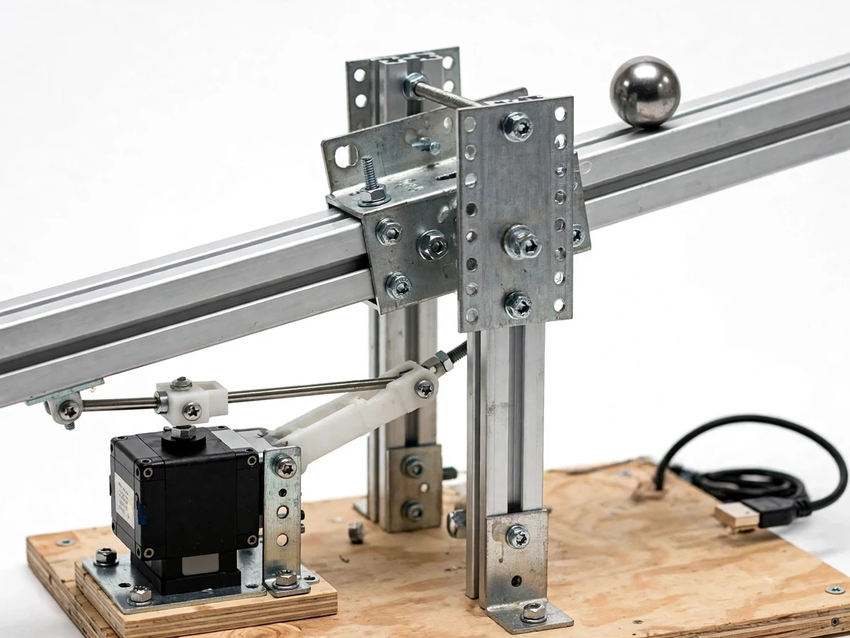
The ball and beam is the canonical teaching rig for feedback control because it is simple to see and hard to tame: the ball accelerates away from any tilt, so only a well-tuned controller can hold it still. Students of control theory usually meet PID as equations on a slide; this project makes it physical. An ultrasonic sensor measures the ball's position along the beam, an Arduino runs the PID loop, and a servo tilts the beam through a linkage arm to drive the ball toward the setpoint. The real learning is the tuning: starting from proportional-only oscillation, adding derivative to damp it, and discovering what integral does to steady-state error — each stage documented with response plots from the student's own rig. It is the rare project where the viva practically runs itself.
How it works
- The steel ball rests on the aluminium beam; the ultrasonic sensor at one end continuously measures the ball's distance (position).
- The Arduino reads the position, computes the error against the setpoint, and runs the PID calculation each control cycle.
- The PID output drives the servo, which tilts the beam through the linkage arm — tilting toward the ball to slow it, away to accelerate it back.
- With proportional control only, the ball oscillates; the student increases derivative gain to damp the oscillation.
- Integral gain is added to remove the steady-state offset, with anti-windup preventing overshoot after large disturbances.
- The tuned system holds the ball at the setpoint and recovers from a finger-tap disturbance — the standard live demo.
- Position data logged over serial produces step-response plots for the report, documenting each tuning stage quantitatively.
Tech stack:
- Arduino Uno (PID controller)
- Ultrasonic distance sensor
- High-torque servo motor
- Aluminium beam + pivot frame
- Linkage arm mechanism
- Serial data logging
- 5–6 V servo power supply
- PID tuning procedure
| Parameter | Value |
|---|---|
| Controller | Arduino Uno (ATmega328P) — datasheet |
| Position sensor | Ultrasonic, approximately 2–40 cm usable range (expected) |
| Actuator | High-torque servo, approximately 10 kg·cm (datasheet class) |
| Beam | Aluminium, approximately 60 cm (prototype) |
| Ball | Steel, approximately 40 mm diameter (prototype) |
| Control rate | Approximately 50 Hz loop (firmware, design) |
| Setpoint modes | Hold, step change, sine track (firmware) |
| Power | 5–6 V DC servo supply + USB/5 V logic (design) |
Project features
- [Full PID implementation] Position PID loop running on the Arduino with configurable Kp, Ki and Kd — the student tunes all three terms experimentally, not just in simulation.
- [Ultrasonic ball tracking] An ultrasonic sensor at the beam end measures ball position continuously, demonstrating real sensor feedback with noise and dead zones.
- [Servo-linkage actuation] A high-torque servo drives the beam through a mechanical linkage, showing how control signals become physical motion.
- [Setpoint control modes] Hold-position, step-change and (firmware option) sine-tracking modes let the student demonstrate different control scenarios.
- [Live tuning interface] PID gains adjustable via serial commands or potentiometers, so tuning iterations happen in seconds during the demo.
- [Response plotting] Logged position-vs-time data exports for step-response plots — the evidence section of the report comes from the student's own rig.
- [Anti-windup and filtering] Integral anti-windup and sensor filtering implemented in firmware, teaching the practical details textbooks gloss over.
What is included
- Ball-and-beam rig (assembled: beam, pivot, servo, linkage, sensor)
- Arduino controller (programmed with PID firmware)
- Complete firmware source code with gain-adjustment interface
- PID tuning procedure document (Ziegler-Nichols + manual method)
- Wiring diagram and mechanical assembly guide
- Data-logging guide for response plots
- Project report PDF (background, control theory, tuning study, results)
- PPT presentation for final review
- Viva Q&A preparation document (PID terms, stability, tuning, anti-windup)
Limitations & prerequisites
- The ultrasonic sensor has a dead zone and noise; position accuracy is approximately ±5 mm, which the report states honestly.
- The rig balances one ball on one axis — it does not demonstrate multi-axis or nonlinear control beyond this plant.
- Servo backlash and linkage play limit the achievable precision; the tuning guide works within these mechanical realities.
- Aggressive gains cause oscillation or ball drop-off — the tuning procedure approaches stability conservatively by design.
- Step-response figures in the report come from the student's own rig and tuning session, presented as measured-on-prototype.
- The beam must be level-calibrated at setup; the procedure document covers this buyer-run step.
Frequently Asked Questions
How does the PID controller actually work here?
The ultrasonic sensor reports ball position; the Arduino computes the error from the setpoint and combines three terms — proportional (push harder when far), integral (remove persistent offset), derivative (damp oscillation) — into a servo command that tilts the beam every control cycle.
How do I tune the PID gains?
The included procedure starts with proportional-only to find oscillation, adds derivative to damp it, then adds integral for steady-state accuracy — with Ziegler-Nichols as the systematic alternative. Each stage is documented with plots from your own rig.
What does the demo look like?
The ball holds a setpoint on the beam; you tap it with a finger and watch it recover. Changing the setpoint shows a clean step response. It is one of the most visually convincing control demos.
Why an ultrasonic sensor instead of a camera?
It is robust, cheap and fast enough for the control loop, and its noise and dead zone teach real sensor limitations — which the report discusses as part of the engineering.
Can it track a moving setpoint?
Yes — the firmware includes a sine-tracking mode where the setpoint oscillates and the ball follows, demonstrating tracking performance beyond simple regulation.
Is this project suitable for a final-year project?
Yes — for Mechanical, Electrical and Electronics programs. It is the standard hands-on vehicle for feedback control, PID tuning and mechatronic integration. Suitable for B.E./B.Tech final-year projects in Mechanical, Electrical and Electronics.
Components & software requirements
- Arduino Uno (PID controller)
- Ultrasonic distance sensor
- High-torque servo motor
- Aluminium beam + pivot frame
- Linkage arm mechanism
- Serial data logging
- 5–6 V servo power supply
- PID tuning procedure
Delivery information
Built-to-order project. Delivery timeline is shared after order confirmation based on current queue.
Support terms
Complete documentation, setup guide, and viva preparation included. Support for setup and explanation provided.