
More project photos (3)
The problem
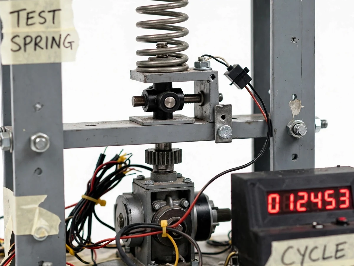
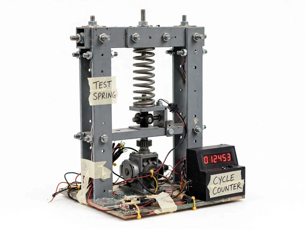
Most mechanical failures are fatigue failures: parts break under repeated loads far below their static strength — valve springs, suspension springs, fasteners. The S-N curve that predicts fatigue life is measured on dedicated rigs that cycle specimens thousands of times, equipment most colleges cannot afford per batch. A benchtop spring fatigue tester fills this teaching gap: a motor drives a cam that compresses a coil spring once per revolution while a digital counter tracks every cycle, letting students run real fatigue trials and observe crack initiation, stiffness loss and permanent set. Running several springs at different deflections builds a classroom dataset that shows cycle life falling as stress amplitude rises — the core fatigue lesson, demonstrated on hardware instead of a blackboard.
Measures free length with a vernier caliper and inspects the spring.
Follow the working sequence
How it works
- A coil spring is seated between the rig's plates and the deflection is set via the cam and follower height.
- The starting free length is measured with a vernier caliper and recorded on the observation sheet.
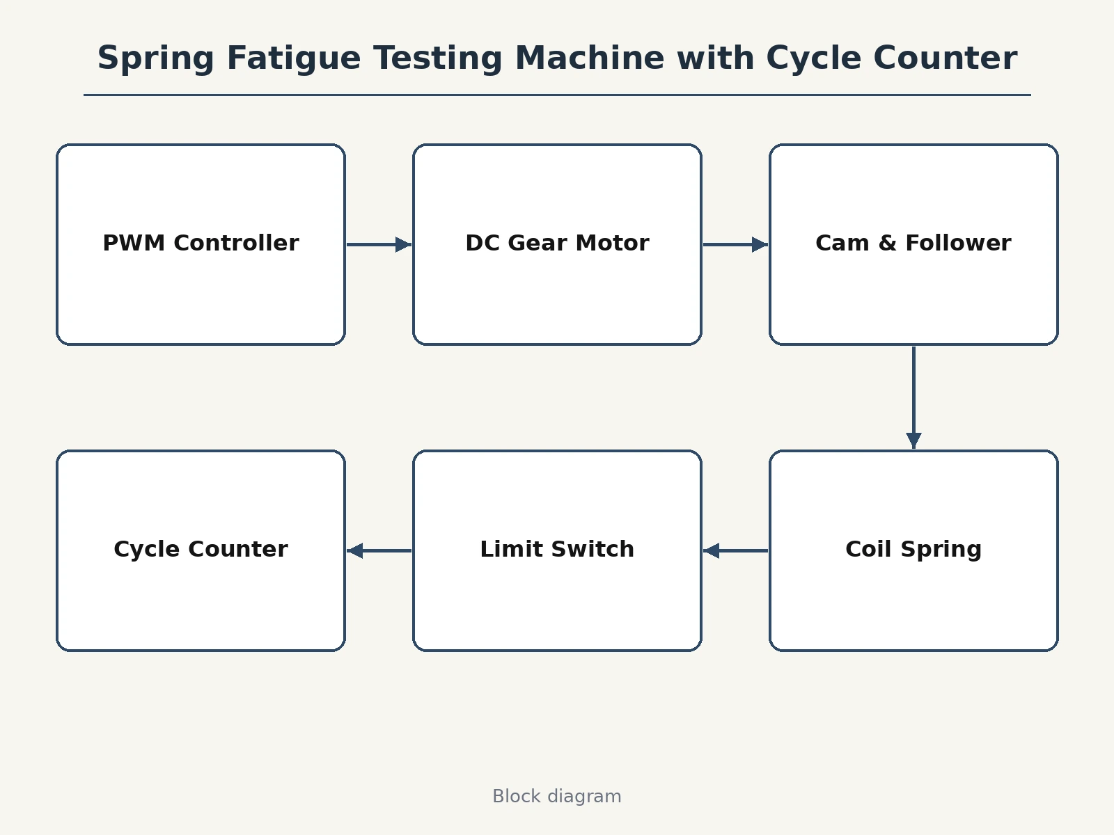
- The motor is started at the controller-set speed; the cam compresses and releases the spring once per revolution.
- A limit switch on the follower fires each cycle and the digital counter increments on the LED display.
- At the target count the rig is stopped; free length is re-measured and the spring is inspected for cracks and permanent set.
- Repeating at several deflections shows how cycle life falls as stress amplitude rises — the fatigue lesson in the student's own data.
Tech stack:
- MS angle/plate frame fabrication
- Cam-and-follower mechanism
- DC gear motor with PWM speed controller
- Digital cycle-counter module with limit-switch trigger
- Test coil springs (sourced/fabricated)
- Vernier caliper for free-length measurement
| Parameter | Value |
|---|---|
| Drive | DC gear motor with PWM speed controller |
| Cycling | 1 compression-release per cam revolution (design) |
| Counter | Digital LED module, limit-switch triggered |
| Deflection | Adjustable via cam and follower height |
| Frame | MS angle and plate, fabricated |
| Measurement | Vernier caliper free-length checks, visual crack inspection |
| Test articles | Coil springs, multiple deflection levels |
Project features
- [Cam-and-follower cycling] A motor-driven cam compresses the coil spring once per revolution — simple, repeatable cyclic loading with no hydraulics.
- [Digital cycle counter] Every cycle is counted on an LED display, triggered by a limit switch on the follower, so long runs need no supervision.
- [Adjustable deflection] Cam selection and follower height set the spring deflection, letting students test at several stress amplitudes.
- [Speed-controlled motor] A PWM controller sets the cycling rate; students can trade test speed against observation comfort.
- [Rigid test frame] Fabricated MS frame keeps the spring, cam and follower aligned through thousands of cycles.
- [Observation sheets] The manual's sheets record free length, crack checks and stiffness before and after each run.
- [Classroom S-N dataset] The procedure is designed so a batch of students builds a shared deflection-vs-life dataset.
What is included
- Working spring fatigue testing machine
- Fabrication drawings (frame, cam, follower, spring seats)
- Wiring documentation (motor, controller, counter, limit switch)
- Experiment manual with observation sheets
- Set of test coil springs
- Project report PDF (fatigue theory, S-N concept, rig design)
- PPT presentation for final review
- Viva Q&A preparation document (fatigue, endurance limit, S-N curves, crack initiation)
Limitations & prerequisites
- Tests coil springs in compression cycling only — tension and bending fatigue need different fixtures.
- Cycle counts are comparative classroom data, not certified material qualification.
- Deflection settings are discrete (cam/follower positions), not continuously variable load control.
- No automatic crack detection — inspection is visual and manual.
Frequently Asked Questions
What does the counter actually count?
Complete compression-release cycles: a limit switch on the follower fires once per cam revolution and increments the digital display.
How long does a test take?
It depends on the target count and motor speed — the counter lets long runs proceed unattended, and the manual suggests count plans per deflection level.
What do students observe after a run?
Change in free length (permanent set), visible cracks, and stiffness change — all recorded on the observation sheets.
Can it test other parts?
The rig is built for coil springs; other geometries would need new seats and cams, documented as future scope.
Is this project suitable for a final-year project?
Yes — for Mechanical Engineering programs. It makes fatigue — usually a purely theoretical topic — into a hands-on experiment with real cycle data. Suitable for B.E./B.Tech final-year projects in Mechanical Engineering.
Components & software requirements
- MS angle/plate frame fabrication
- Cam-and-follower mechanism
- DC gear motor with PWM speed controller
- Digital cycle-counter module with limit-switch trigger
- Test coil springs (sourced/fabricated)
- Vernier caliper for free-length measurement
Delivery information
Built-to-order project. Delivery timeline is shared after order confirmation based on current queue.
Support terms
Complete documentation, setup guide, and viva preparation included. Support for setup and explanation provided.
Download free synopsis (PDF)
Enter your name and WhatsApp number — the synopsis PDF downloads immediately. We may send occasional project updates on WhatsApp; no spam.