
More project photos (3)
The problem
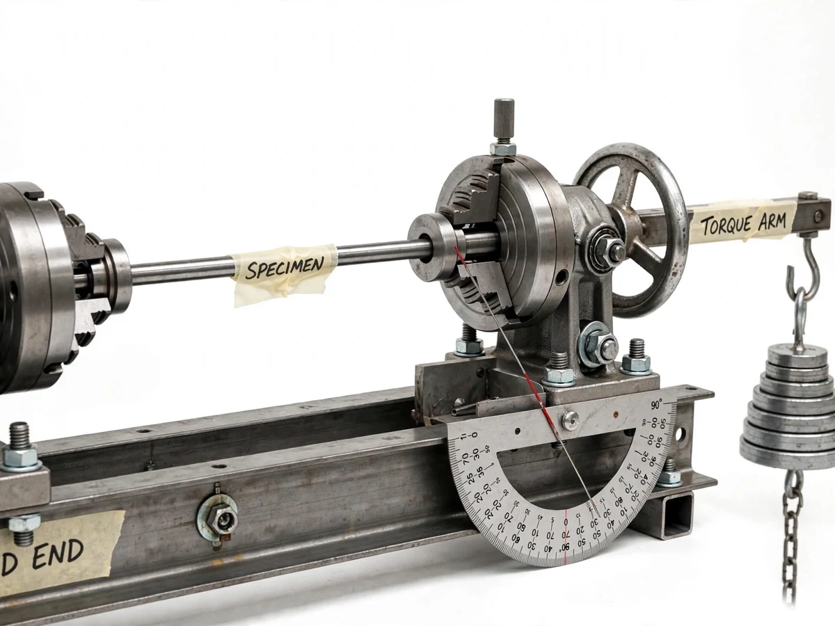
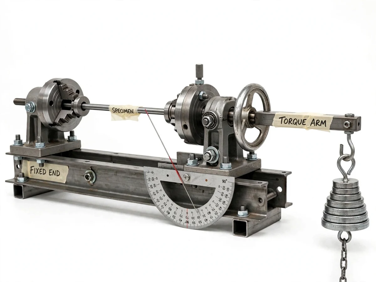
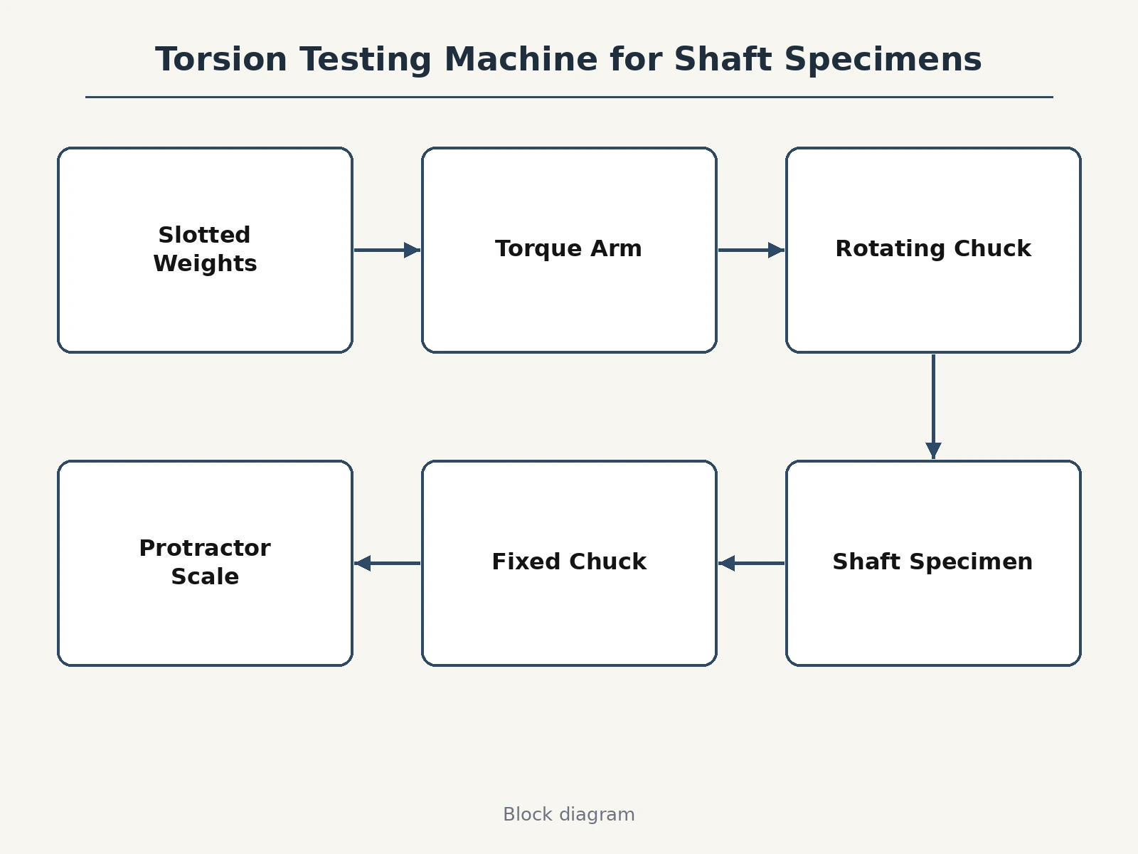
Every transmission shaft, axle and drive coupling lives in torsion — yet the torsion test is the strength-of-materials experiment students most often skip, because commercial torsion machines are costly and usually booked solid in the shared lab. The theory is elegant: torque over angle of twist gives the modulus of rigidity, and the torque-twist curve reveals elastic limit, yielding and fracture in shear. This project provides a student-built torsion testing machine that makes the whole experiment hands-on. A slender shaft specimen is gripped between a fixed headstock chuck and a rotating chuck; a torque arm bolted near the rotating end carries a weight hanger, so each added weight applies a known torque; a pointer on the rotating chuck sweeps a protractor scale to read the angle of twist. The student loads in steps, records torque versus twist, plots the curve, computes the modulus of rigidity, and repeats on brass and aluminium specimens for comparison.
Grip the shaft specimen; the hand-wheel rotates one end for the twist.
Follow the working sequence
How it works
- A shaft specimen is measured (diameter at three points, gauge length) and gripped firmly in both chucks with the headstock set for the chosen gauge length.
- The protractor pointer is zeroed and the weight hanger is hung on the torque arm without weights.
- Slotted weights are added in equal steps; after each addition the angle of twist is read on the protractor once the pointer settles.
- Loading continues in steps through the elastic region; the student notes where the readings stop being proportional — the onset of yielding.
- Torque (weight × arm length) is plotted against angle of twist; the initial slope gives the torsional stiffness.
- The modulus of rigidity is computed from the torsion formula using the measured diameter, gauge length and slope, and compared across the three materials.
- Optionally, one specimen is loaded to fracture and the helical shear failure surface is examined and photographed for the report.
Tech stack:
- Fabricated steel bed with sliding headstock
- Fixed chuck headstock and hand-wheel rotating chuck
- Torque arm with weight hanger (known arm length)
- Slotted cast-iron weights
- 180° protractor scale with pointer, 1° resolution
- Shaft specimens: MS, brass, aluminium
- Vernier caliper for specimen diameter
- Torque-twist workbook and fabrication drawings
| Parameter | Value |
|---|---|
| Specimen size | Approximately 8–12 mm diameter × 300–500 mm gauge length (design target) |
| Torque application | Dead weights on torque arm, approximately 200 mm arm (design target) |
| Max torque | Approximately 20 N·m with full weight set (design target) |
| Angle readout | Protractor, 0–180°, 1° resolution (instrument spec) |
| Materials supplied | MS, brass, aluminium shaft specimens |
| Bed length | Approximately 800 mm fabricated steel bed (design target) |
| Output | Torque-twist curve and modulus of rigidity from student readings |
Project features
- [Fixed and rotating chucks] A fixed headstock chuck and a hand-wheel-driven rotating chuck grip the specimen positively, so torque is transmitted without slip at both ends.
- [Dead-weight torque loading] A torque arm of known length carries a weight hanger; each slotted weight added applies a precisely known torque — no torque sensor needed, the physics is transparent.
- [Protractor angle readout] A large protractor scale with a pointer on the rotating chuck reads angle of twist directly to 1°, giving the student clean torque-twist data.
- [Three-material specimen set] Shaft specimens in mild steel, brass and aluminium are supplied so the modulus of rigidity is determined and compared across materials.
- [Adjustable gauge length] The headstock slides on the bed to set the specimen gauge length, letting the student verify that twist is proportional to length.
- [Torque-twist plotting workbook] Observation tables and graph sheets walk the student from raw readings to the rigidity modulus via the torsion formula.
- [Fracture demonstration] The machine can be loaded to specimen fracture, showing the shear failure surface — a memorable, discussable viva moment.
What is included
- Complete torsion testing machine (assembled and tested)
- Specimen set: MS, brass, aluminium shafts
- Slotted weight set with hanger
- Vernier caliper for diameter measurement
- Torque-twist observation tables and calculation workbook
- Fabrication drawings of the machine
- Project report PDF (theory, procedure, readings, analysis)
- PPT presentation for final review
- Viva Q&A preparation document (torsion formula, rigidity modulus, shear failure)
Limitations & prerequisites
- Angle of twist is read manually on a protractor to 1°, so the rigidity modulus carries typical ±3–5% combined error from angle, diameter and arm-length measurements — the report works this through honestly.
- The hand-wheel rotating chuck applies torque quasi-statically; dynamic or fatigue torsion is out of scope.
- Specimens are limited to the supplied diameters and the machine's grip range; very large or very short specimens cannot be mounted.
- Fracture loading is a one-way demonstration per specimen; spare specimens are limited to the supplied set.
- Results are for academic comparison, not certified material testing.
Frequently Asked Questions
What does the student actually measure?
Applied torque (from known weights × arm length) and the resulting angle of twist on the protractor, step by step — the torque-twist curve is the core result.
How is the modulus of rigidity found?
From the initial slope of the torque-twist curve using the torsion formula, with the specimen diameter and gauge length the student measures themselves.
Why three materials?
Steel, brass and aluminium have widely different rigidity moduli, so the comparison makes the experiment's conclusion robust and gives the viva real content.
Can the machine break a specimen?
Yes — loaded far enough, a specimen fractures in shear with the classic helical surface, which makes an excellent report photograph and viva discussion.
Is this the same as a UTM torsion attachment?
No. This is a standalone, dead-weight machine the student operates and understands completely — the torque path has no black boxes.
Is this project suitable for a final-year project?
Yes — for Mechanical and Civil programs. It is a real materials-testing machine producing measured stress–strain behaviour in torsion. Suitable for B.E./B.Tech final-year projects in Mechanical and Civil Engineering.
Components & software requirements
- Fabricated steel bed with sliding headstock
- Fixed chuck headstock and hand-wheel rotating chuck
- Torque arm with weight hanger (known arm length)
- Slotted cast-iron weights
- 180° protractor scale with pointer, 1° resolution
- Shaft specimens: MS, brass, aluminium
- Vernier caliper for specimen diameter
- Torque-twist workbook and fabrication drawings
Delivery information
Built-to-order project. Delivery timeline is shared after order confirmation based on current queue.
Support terms
Complete documentation, setup guide, and viva preparation included. Support for setup and explanation provided.
Download free synopsis (PDF)
Enter your name and WhatsApp number — the synopsis PDF downloads immediately. We may send occasional project updates on WhatsApp; no spam.