
More project photos (2)
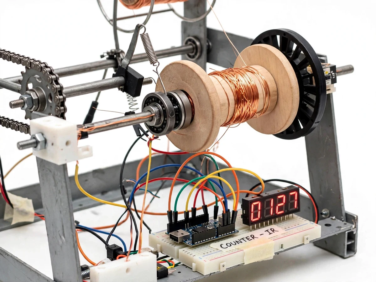
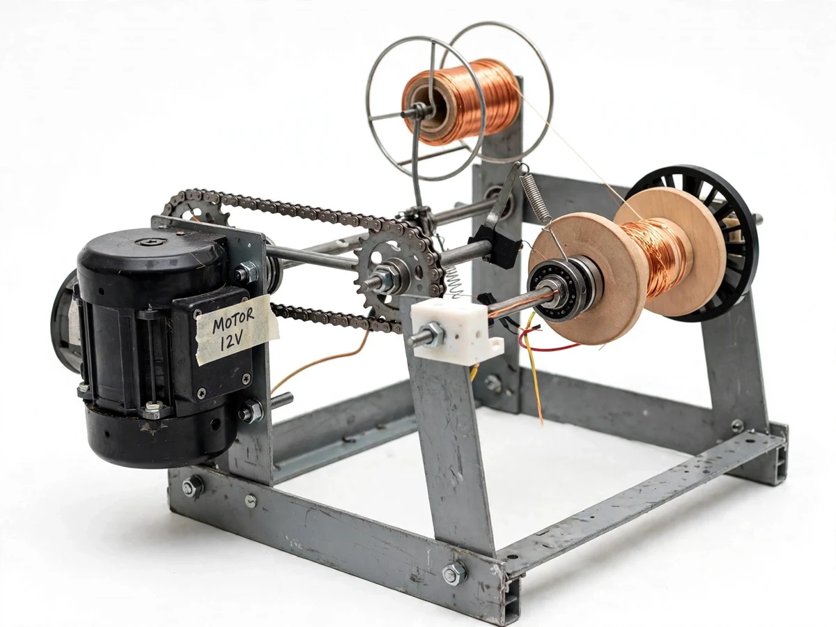
The problem
Hand-winding transformer and inductor coils is slow, tiring, and unreliable: the turn count is guessed, tension varies along the length, and uneven layers waste wire and produce inconsistent coils. Commercial winding machines solve this but are far too expensive for a college lab, and off-the-shelf coil kits teach the student nothing about how a winder actually works. This project builds the machine itself — a bench-top automatic coil winder with a 12V DC geared motor driving a bobbin mandrel through a chain-sprocket reduction, a digital turn counter that stops the motor at a preset number of turns, and a mechanical tensioner that keeps the wire taut throughout the wind. It is a real machine-design build: frame fabrication, shaft and bearing selection, speed reduction, and a small embedded counter loop. Students demonstrate it by winding coils for a small transformer or a laboratory inductor and explaining the drive calculations, tension mechanics and counter logic in the viva.
Operator foot switch that starts the winding cycle on the machine.
Follow the working sequence
How it works
- The operator mounts an empty bobbin on the mandrel, threads wire from the supply spool through the tensioner arm and guide block, and ties the wire start to the bobbin.
- The target turn count is keyed in on the push buttons; the Arduino stores it and shows the current count (zero) on the 7-segment display.
- Pressing the footswitch starts the 12V DC geared motor; the chain-sprocket reduction turns the bobbin at a steady speed set by the PWM knob.
- The tensioner arm keeps a constant drag on the incoming wire while the operator slides the guide block laterally to lay turns evenly across the bobbin width.
- Each spindle revolution triggers the IR slot sensor; the Arduino debounces the pulse and increments the displayed turn count.
- When the count reaches the preset, the firmware switches the motor driver off and the spindle coasts to a stop; the operator cuts and tapes the wire end.
- The finished coil's turn count is verified against the display before the next coil is started — a repeatable, documented winding procedure.
Tech stack:
- 12V DC geared motor
- Chain-sprocket drive
- Arduino Nano
- IR slot sensor
- L298N motor driver (PWM)
- 4-digit 7-segment display
- MS angle frame, pillow-block bearings
- Footswitch
| Parameter | Value |
|---|---|
| Drive | 12V DC geared motor, chain-sprocket reduction to spindle (approximately 3:1, design target) |
| Spindle speed | Approximately 0–120 RPM (PWM adjustable, design target) |
| Turn counter | IR slot sensor + Arduino Nano, 4-digit 7-segment display, 0–9999 turns |
| Preset auto-stop | Push-button settable; motor cut at preset with small inertial overrun (speed-dependent, typically under one turn) |
| Wire size | Enamelled copper wire, approximately 0.2–1.0 mm diameter (design target) |
| Bobbin capacity | Diameter approximately up to 120 mm, width approximately up to 100 mm (design target) |
| Tensioner | Spring-loaded pivot arm with friction pad, adjustable spring pre-load |
| Power supply | 12V DC, approximately 5A SMPS adapter (motor + logic) |
| Operation | Footswitch start/stop, both hands free for wire guiding |
| Frame | MS angle frame with pillow-block spindle bearings |
Project features
- [Motor-driven winding spindle] A 12V DC geared motor drives the bobbin mandrel through a chain-and-sprocket reduction, giving steady, controllable winding torque — no hand cranking, no guessing.
- [Digital turn counter] An IR slot sensor reads a slotted disc on the spindle shaft; an Arduino Nano counts each revolution and shows the running total on a 4-digit 7-segment display.
- [Preset turn auto-stop] The target turn count is set with push buttons; the firmware cuts the motor when the preset is reached, so coils are wound to an exact repeatable count.
- [PWM speed control] The motor driver takes a PWM signal from the Arduino, so winding speed is set with a control knob — slow for the first laying turns, faster once the coil is established.
- [Spring-loaded wire tensioner] A pivoting tensioner arm with a spring and friction pad holds the wire at constant drag from the supply spool to the bobbin, keeping layers tight and even.
- [Interchangeable bobbin mandrel] The mandrel shaft accepts different bobbin widths and diameters with simple shaft collars, so several coil sizes can be wound on the same machine.
- [Footswitch operation] A footswitch starts and stops winding, leaving both hands free to guide the wire — the same hands-free practice used on real winding benches.
- [Rigid bearing-mounted frame] The spindle and motor sit on pillow-block bearings in an MS angle frame, keeping the winding axis stable under chain tension.
What is included
- Working coil winding machine prototype (motor, chain drive, frame, tensioner, counter electronics)
- Arduino Nano firmware source code (counter, preset logic, PWM speed control)
- Wiring diagram and component connection notes
- Complete bill of materials with specifications
- Turn-counter verification procedure (known-turn calibration check to run before each winding session)
- Winding procedure guide (threading, tension setting, speed selection, finishing)
- Project report PDF (design, drive calculations, methodology, results)
- PPT presentation for final review
- Viva Q&A preparation document (machine design, motor selection, sensor interfacing, firmware logic)
Advantages
- Motor-driven winding spindle: a 12 V DC geared motor drives the bobbin mandrel through a chain-sprocket reduction (approximately 3:1), giving steady, controllable winding torque — no hand cranking, no guessed turns.
- Digital turn counter with preset auto-stop: an IR slot sensor on the spindle feeds an Arduino Nano that shows the running count on a 4-digit 7-segment display (0–9999 turns) and cuts the motor at the button-preset target, so coils are wound to an exact, repeatable count.
- Constant wire tension from a spring-loaded pivoting tensioner arm with friction pad and adjustable spring pre-load, keeping layers tight and even from the supply spool to the bobbin.
- Speed matched to the job: PWM drive through the L298N lets the operator start slow for the first laying turns and speed up once the coil is established, and a footswitch leaves both hands free to guide the wire — the same practice used on real winding benches.
- Interchangeable mandrel with simple shaft collars accepts several bobbin widths and diameters (approximately up to 120 mm diameter, 100 mm width), so the same machine winds different coil sizes. Deliverables: Arduino firmware, wiring diagram, BOM, turn-counter verification procedure, winding procedure guide, report PDF, PPT and viva Q&A.
Disadvantages
- Turn-count accuracy depends on the IR sensor's gap and disc alignment — a dirty or misaligned sensor can miss or double-count revolutions, so the included known-turn verification procedure must be run before each session.
- Layer evenness is operator-guided: the wire guide is slid by hand, so wide bobbins can develop overlapped layers if the guide moves unevenly.
- The preset auto-stop cuts motor power, but spindle inertia causes a small overrun — typically under one turn at low speed, more at high speed — so the preset must be set with that in mind.
- Wire range is limited to enamelled copper around 0.2–1.0 mm; very thick wire, flat strip and toroidal cores are not supported, and chain slack plus bearing clearances make this a student prototype with visibly looser tolerances than an industrial winder.
Limitations & prerequisites
- Turn-count accuracy depends on IR sensor gap and disc alignment; run the included known-turn verification procedure before each session — a dirty or misaligned sensor can miss or double-count revolutions.
- Winding evenness is operator-guided (the wire guide is slid by hand); wide bobbins can develop overlapped layers if the operator moves the guide unevenly.
- The preset auto-stop cuts power, but spindle inertia causes a small overrun — typically under one turn at low speed, more at high speed; plan the preset accordingly.
- Speed and torque vary with wire gauge and supply voltage; wire near the 1.0 mm end of the range needs lower winding speed to keep tension steady.
- Chain slack and bearing clearances give approximate mechanical alignment — this is a student prototype, not an industrial winding machine, so tolerances are visibly looser.
- Designed for enamelled copper wire around 0.2–1.0 mm; very thick wire, flat strip, or toroidal cores are not supported by this build.
Frequently Asked Questions
Which controller is used?
An Arduino Nano. It reads the IR slot sensor pulses, debounces them, drives the 4-digit 7-segment turn display, handles the preset push buttons, and outputs the PWM signal to the L298N motor driver.
How does the turn counter work?
A slotted disc fixed to the spindle shaft passes through an IR slot sensor once per revolution. Each passing edge generates a pulse that the Arduino counts after software debouncing. The counter can be zeroed and a target turn count can be preset, at which point the firmware switches the motor off.
Can the winding speed be changed?
Yes — a control knob feeds a speed setting to the Arduino, which adjusts the PWM duty cycle to the L298N motor driver. Typical practice is to start slow for the first few laying turns and increase speed once the coil is established.
Can it wind different coil sizes?
The mandrel accepts bobbins of different widths and diameters within the capacity range (approximately up to 120 mm diameter and 100 mm width) using shaft collars. Very large bobbins or toroidal cores would need a different mandrel, which can be fabricated as a customization.
Is the coil quality consistent?
The turn count and tension are repeatable, which is the hard part of hand winding. Layer evenness depends on the operator sliding the guide evenly — it improves with practice, and the winding guide documents the technique. A motorized traversing guide can be added as a customization.
Is this project suitable for a final-year project?
Yes — for Mechanical, Electrical and E&TC programs. It demonstrates machine design (drive and bearing selection), fabrication, power transmission, sensor interfacing and embedded firmware, all in one genuinely buildable prototype. Suitable for B.E./B.Tech final-year projects in Mechanical, Electrical and E&TC.
Components & software requirements
- 12V DC geared motor
- Chain-sprocket drive
- Arduino Nano
- IR slot sensor
- L298N motor driver (PWM)
- 4-digit 7-segment display
- MS angle frame, pillow-block bearings
- Footswitch
Delivery information
Built-to-order project. Delivery timeline is shared after order confirmation based on current queue.
Support terms
Complete documentation, setup guide, and viva preparation included. Support for setup and explanation provided.
Download free synopsis (PDF)
Enter your name and email — the synopsis PDF downloads immediately. We may send occasional project updates; no spam, unsubscribe anytime.