
More project photos (2)
The problem
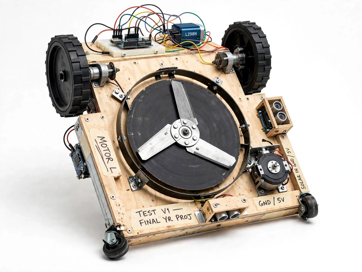
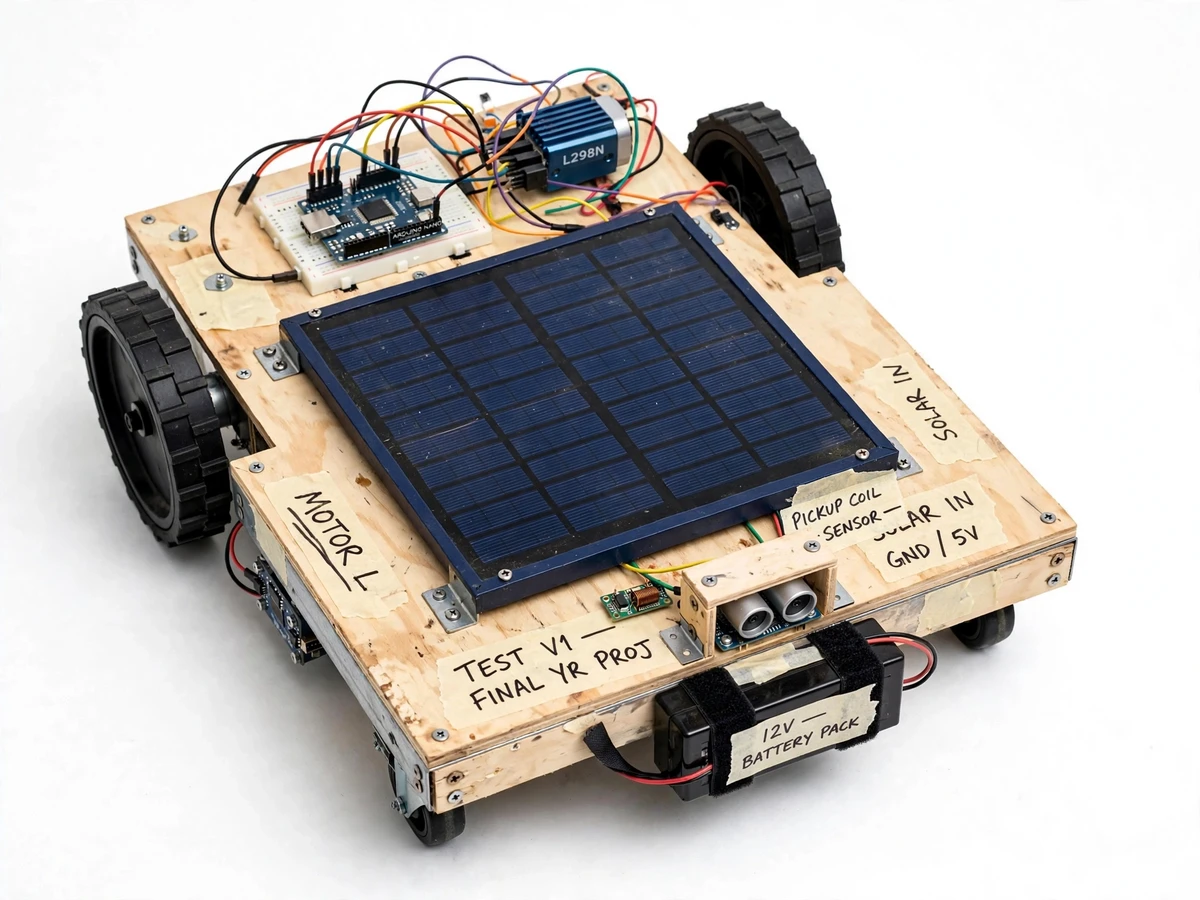
Keeping a lawn mowed is repetitive manual work, and commercial robotic mowers — while capable — are expensive sealed products that teach a student nothing about how they work. The real engineering problem is the closed loop: how does a small machine stay inside a yard it cannot see, dodge a garden chair, and never run its blades into someone's foot? This project answers that with a student-built mower. A steel-and-plywood chassis on four wheels carries a spinning three-blade cutting disc underneath; a top-mounted solar panel trickle-charges the 12 V battery pack; and an Arduino Nano runs the whole navigation loop. A perimeter wire laid around the lawn carries a low-frequency signal, an inductive pickup coil on the mower senses the edge and turns the machine back inside, an ultrasonic sensor plus a bump switch handle obstacles, and a lift/tilt interlock stops the blades the instant the mower is picked up. Nothing is simulated — the wire, the sensors and the blades are all real and demonstrable.
Inductive coil with an amplifier-rectifier stage detecting the boundary wire's 5 kHz signal; the signal collapses as the coil crosses the wire.
Follow the working sequence
How it works
- The buyer lays a single loop of insulated copper wire around the lawn perimeter, staked flush with the ground, and connects both ends to the boundary generator unit, which pushes a roughly 5 kHz signal current through the loop.
- The mower's inductive pickup coil feeds an amplifier-rectifier stage into the Arduino Nano; inside the loop the detected signal is strong, and it collapses as the coil crosses the wire.
- When the signal drops below the tuned threshold, the firmware stops both drive motors, reverses for about one second, then executes a differential turn back toward the interior and resumes forward mowing.
- The HC-SR04 ultrasonic sensor pings roughly ten times per second; an obstacle inside the 25 cm stop zone triggers the same stop-reverse-turn sequence.
- If the mower physically touches something the sensor beam missed, the front bump switch forces an immediate stop and turn, overriding all other motion commands.
- The cutting motor spins the three-blade disc at a design target of about 3,000 RPM only while the chassis sits level; the tilt/lift interlock kills the cutting motor within a second of pickup or tip-over, and cutting resumes only when the mower is set back down flat.
- While it works, the 10 W solar panel trickle-charges the 12 V battery pack; a low-voltage cutoff disables the drive and cutting motors when the pack runs low, protecting the battery from deep discharge.
Tech stack:
- Arduino Nano (ATmega328P), firmware in C/C++ via Arduino IDE
- L298N dual H-bridge motor driver
- 2 × 12 V DC gear motors (design about 100 RPM) + 2 caster wheels
- HC-SR04 ultrasonic range sensor
- Inductive pickup coil with amplifier/rectifier boundary detector
- 12 V battery pack with solar charge-control stage
- 10 W, 12 V nominal solar panel, top-mounted
- DC cutting motor with steel disc and 3 replaceable blades
| Parameter | Value |
|---|---|
| Cutting width | 20 cm (design target) |
| Blade speed | 3,000 RPM (design target) |
| Cutting height | 2–6 cm, deck adjustable (design) |
| Drive motors | 2 × 12 V DC gear motors, about 100 RPM (design) |
| Battery | 12 V, 7 Ah sealed lead-acid pack (design) |
| Solar panel | 10 W, 12 V nominal, top-mounted (design) |
| Boundary loop | Up to 150 m insulated copper wire, about 5 kHz loop signal (design) |
| Obstacle detection | HC-SR04, up to 4 m range; stop-and-turn at about 25 cm (design threshold) |
| Chassis footprint | Approximately 40 × 30 cm steel/plywood deck (design) |
| Weight | Approximately 6–8 kg without the boundary kit (expected) |
| Run time | Up to about 45 min on a full charge under light grass load (design target, not measured) |
Project features
- [Boundary-wire navigation] A copper wire loop laid around the lawn carries a low-frequency signal; the mower's inductive pickup coil detects the signal edge, and the firmware commands a reverse-turn maneuver to steer the machine back inside the loop.
- [Ultrasonic obstacle avoidance] An HC-SR04 sensor scans the path ahead; when an object enters the stop zone at around 25 cm, the mower stops, reverses briefly and turns away before resuming its path.
- [Bump-switch fallback] A front-mounted limit switch is the last line of defense — any physical contact triggers an immediate stop and turn, independent of the ultrasonic sensor.
- [Three-blade cutting deck] A DC motor under the chassis spins a steel disc fitted with three replaceable blades; cutting height adjusts between 2 and 6 cm by repositioning the deck.
- [Blade safety interlock] A tilt/lift switch cuts power to the cutting motor within a second of the mower being picked up or tipped; the blades spin only while the chassis sits flat.
- [Solar trickle charging] The top-mounted 10 W panel feeds the 12 V battery through a charge-control stage whenever light hits it, extending run time and keeping the pack topped up between sessions.
- [Differential-drive steering] Two 12 V DC gear motors drive the rear wheels through an L298N bridge, giving forward, reverse and in-place turns — everything the wire-following and avoidance maneuvers need.
What is included
- Working built-to-order mower prototype (chassis, drive, cutting deck, electronics)
- Boundary-wire generator unit with wire, ground stakes and setup guide
- Arduino Nano firmware: boundary detection, avoidance, blade interlock, low-voltage cutoff
- Wiring diagram and mechanical parts list with assembly notes
- Solar charge-control circuit notes and battery care guide
- Setup procedure: laying the wire, tuning the pickup threshold, adjusting cutting height
- Project report PDF (navigation theory, circuit design, build log)
- PPT presentation for final review
- Viva Q&A preparation document
Limitations & prerequisites
- Designed for small, fairly flat lawns (up to about 100 m², slopes under about 10°); bumpy or steep ground defeats the small wheels and can false-trigger the tilt interlock.
- A 20 cm cutting width makes it a demonstration-scale mower, not a replacement for a commercial unit; dense or tall grass can stall the cutting motor.
- The solar panel trickle-charges the pack — it extends run time but cannot power the mower indefinitely on a cloudy day; heavy grass load shortens every number in the spec table.
- The boundary wire must be laid, pinned and tested by the buyer; a broken or gapped loop stops navigation until repaired.
- Navigation is wire-following plus ultrasonic avoidance only — no GPS, no phone app, no rain sensing.
- Buried metal objects or power cables near the wire can distort the inductive signal and need a retest after the wire is laid.
- The blades are real sharpened steel: the interlock is a safety layer, not a substitute for keeping hands clear while the blades spin.
Frequently Asked Questions
How does the boundary wire navigation actually work?
A loop of insulated copper wire around the lawn carries a roughly 5 kHz signal from a small generator unit. The mower carries an inductive pickup coil; inside the loop the detected signal is strong, outside it collapses. The Arduino watches this and commands a reverse-turn maneuver whenever the signal drops, so the machine works its way around inside the yard without ever crossing the wire.
What happens when it meets an obstacle?
The front HC-SR04 ultrasonic sensor watches the path ahead and triggers the stop-reverse-turn sequence at about 25 cm. If the mower still touches something the sensor beam missed, the front bump switch forces an immediate stop and turn. Both paths are demonstrated in the acceptance run.
How long does it run, and what does the solar panel actually do?
Run time is a design target of up to about 45 minutes on a full 12 V, 7 Ah pack under light grass load — it is not claimed as a measured figure until tested on the built unit. The 10 W panel trickle-charges the battery in sunlight, extending sessions and keeping the pack topped up between uses; it does not run the mower on solar power alone.
Do I have to lay the boundary wire myself?
Yes — the loop must match your own lawn. The kit includes the wire, stakes and generator unit with a step-by-step laying guide, plus a procedure for walking the perimeter with the mower to confirm the pickup threshold before the first real run.
How safe are the blades during a demo?
The cutting motor only runs when the chassis sits flat: a tilt/lift interlock cuts blade power within a second of the mower being picked up or tipped, and cutting restarts only when it is set back down level. The blades are still real sharpened steel, so hands stay clear while they spin.
Is this project suitable for a final-year project?
Yes — for Mechanical and Electrical programs. It combines chassis fabrication, motor selection and drive control, electromagnetic boundary sensing, ultrasonic avoidance and a real safety interlock — each piece gives the viva something concrete to discuss.
Components & software requirements
- Arduino Nano (ATmega328P), firmware in C/C++ via Arduino IDE
- L298N dual H-bridge motor driver
- 2 × 12 V DC gear motors (design about 100 RPM) + 2 caster wheels
- HC-SR04 ultrasonic range sensor
- Inductive pickup coil with amplifier/rectifier boundary detector
- 12 V battery pack with solar charge-control stage
- 10 W, 12 V nominal solar panel, top-mounted
- DC cutting motor with steel disc and 3 replaceable blades
Delivery information
Built-to-order project. Delivery timeline is shared after order confirmation based on current queue.
Support terms
Complete documentation, setup guide, and viva preparation included. Support for setup and explanation provided.
Download free synopsis (PDF)
Enter your name and email — the synopsis PDF downloads immediately. We may send occasional project updates; no spam, unsubscribe anytime.