
More project photos (2)
The problem
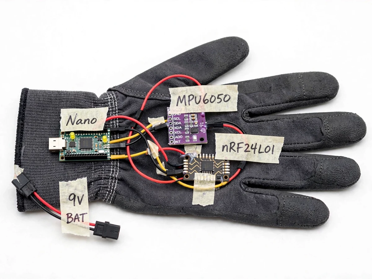
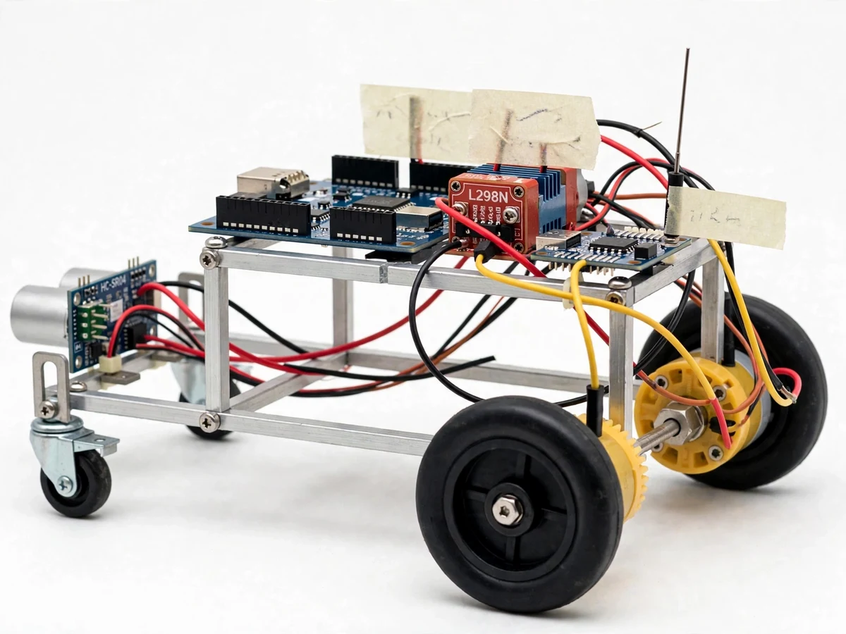
Wheelchair users who cannot operate a joystick — because of limited hand strength or dexterity — have few affordable alternatives, and students rarely get to build and test a working one. The Gesture-Controlled Wheelchair with Obstacle Avoidance (Arduino) demonstrates such an alternative as a small-scale model: the chair is steered by hand tilts instead of a stick. A hand-worn glove carries an Arduino Nano, an MPU6050 accelerometer/gyroscope and an nRF24L01 2.4 GHz transmitter; tilting the hand forward, back, left or right sends a drive command wirelessly to a receiver on the chassis. An Arduino Uno decodes the command and drives two DC gear motors through an L298N dual H-bridge, steering the model by differential drive. An HC-SR04 ultrasonic sensor on the front measures distance continuously: when an obstacle comes within the configured threshold, the chair stops, sounds a buzzer, reverses briefly and turns away. Speed is deliberately capped in firmware for safe indoor demonstration. This is strictly an academic assistive-technology demonstration model — it is not certified and is not a medical mobility device for real patient use.
Nano with MPU6050 on the hand; tilt maps to forward, reverse, left, right or stop.
Follow the working sequence
How it works
- The MPU6050 on the glove samples acceleration and angular velocity over I2C; the Arduino Nano converts hand tilt into one of five commands — forward, reverse, left, right or stop — using configurable tilt-angle thresholds.
- Each command is packed into a small radio packet and sent by the glove's nRF24L01 in the 2.4 GHz ISM band (datasheet) to the matching receiver on the chassis.
- The Arduino Uno decodes the packet and switches the L298N dual H-bridge — up to 46 V / 2 A per channel (datasheet) — driving the two DC gear motors; left/right turns come from different wheel speeds (differential drive).
- In parallel, the front HC-SR04 fires 40 kHz ultrasonic pulses (datasheet) and times each echo to compute the distance ahead, several times per second.
- If that distance falls below the configured obstacle threshold (expected default 25 cm), the firmware overrides the gesture: the chair stops, the buzzer sounds, it reverses briefly and turns toward the clearer side, then resumes the last received gesture command.
- Safety logic runs throughout: a level hand always means stop, top speed is capped in firmware for indoor demos, and a link-loss timeout halts the motors if no valid radio packet arrives.
Tech stack:
- Arduino Nano (gesture glove)
- Arduino Uno (chair receiver)
- MPU6050 accelerometer · gyroscope (I2C)
- nRF24L01 2.4 GHz radio pair
- L298N dual H-bridge motor driver
- HC-SR04 ultrasonic sensor
- Arduino IDE · Embedded C++
- DC gear motors · model-wheelchair chassis
| Parameter | Value |
|---|---|
| Gesture controller | Arduino Nano (ATmega328P), hand-worn glove |
| Chair controller | Arduino Uno (ATmega328P) |
| Motion sensor | MPU6050: ±2/±4/±8/±16 g accel, ±250/±500/±1000/±2000 °/s gyro, I2C (datasheet) |
| Wireless link | nRF24L01, 2.4 GHz ISM band (datasheet); expected range approximately 20–40 m line-of-sight |
| Motor driver | L298N dual H-bridge, up to 46 V / 2 A per channel (datasheet) |
| Obstacle sensor | HC-SR04 ultrasonic, 2 cm–400 cm range, 40 kHz (datasheet) |
| Obstacle threshold | Expected default 25 cm (configurable in firmware) |
| Drive | 2 × DC gear motors, differential steering |
| Top speed | Approximately 0.4 m/s (design target, firmware-capped) |
| Runtime | Approximately 45–60 min mixed demo use (expected, battery-dependent) |
| Power | Glove: 9 V battery; chair: 2S Li-ion pack (both regulated to logic levels) |
| Scale | Tabletop demonstration model — not rideable, not a medical device |
Project features
- [Hand-worn gesture glove] An Arduino Nano with an MPU6050 motion sensor, mounted on a fabric glove, reads hand tilt over I2C and maps it to five commands — forward, reverse, left, right and stop (level hand). Tilt-angle thresholds are configurable in firmware.
- [Wireless 2.4 GHz command link] A matched nRF24L01 pair carries commands from glove to chair with no tether. The receiver applies a link-loss timeout, so the chair halts if the glove leaves range or the radio link drops.
- [Ultrasonic obstacle avoidance] The front HC-SR04 measures distance several times per second. On detecting an obstacle inside the configured threshold, the chair stops, sounds the buzzer, reverses briefly and turns toward the clearer side before resuming the last gesture command.
- [Speed-limited safe demo] Top speed is capped in firmware (design target approximately 0.4 m/s) so the model stays controllable on indoor floors. The cap is a configurable constant for reviewers who ask for it.
- [Differential-drive steering] The Arduino Uno drives two DC gear motors through the L298N dual H-bridge; turns are made by running the wheels at different speeds, keeping the mechanism simple and robust.
- [Onboard status feedback] A buzzer signals obstacle events and command changes, and onboard LEDs mirror the current drive command, so the demonstration is easy to follow from across the room.
- [Compact model-wheelchair chassis] A small tabletop chassis with a seat-like frame, two driven wheels and front casters demonstrates the wheelchair concept at demo scale — plainly a model, not a rideable chair.
What is included
- Working gesture-controlled model-wheelchair prototype (glove unit + chassis)
- Firmware source for both Arduino controllers (gesture mapping + motor/obstacle logic)
- Wiring diagrams and connection documentation
- Component list with part numbers and sourcing notes
- Gesture-calibration guide (tilt thresholds, obstacle distance setup)
- Project report PDF (background, design, methodology, results)
- PPT presentation for final review
- Viva Q&A preparation document (sensors, wireless link, motor control, safety)
- Demonstration guidance
Limitations & prerequisites
- Academic demonstration model only — not certified and not a medical mobility device; it must never be used to move a real person.
- MPU6050 tilt sensing needs calibration and can drift; hand tremor or sudden jerks can trigger unintended commands.
- The HC-SR04 cannot measure closer than about 2 cm (datasheet) and returns weak echoes from soft, angled or sound-absorbing surfaces — obstacle avoidance is a demo aid, not a safety system.
- Indoor, flat-floor use only: small wheels, no suspension, firmware-capped speed (design target approximately 0.4 m/s); stairs, slopes and outdoor terrain are out of scope.
- Radio range is environment-dependent and falls sharply indoors through walls; the link-loss timeout stops the chair, which is the intended safe failure mode.
- Expected runtime of 45–60 minutes of mixed demo use is battery-dependent; continuous driving and frequent obstacle maneuvers drain the pack faster.
- Gesture control is less precise than a joystick — the build makes no claim otherwise, and the report states this plainly.
Frequently Asked Questions
Can a person sit in it or be moved by it?
No. This is a small tabletop model-wheelchair chassis driven by small DC gear motors — it demonstrates gesture steering and obstacle avoidance at demo scale. It is an academic assistive-technology model, not a mobility device, and it is not certified for any patient or passenger use. Nobody should ride it or be moved by it.
Is it a medical device then?
No — and the page states this plainly. It is an academic demonstration model, not certified medical equipment, and it makes no claim about diagnosis, treatment or real patient mobility. It runs at slow indoor demo speeds and is assessed on the engineering: sensor interfacing, wireless control and motor logic.
Which controller and sensors are used?
The hand-worn glove uses an Arduino Nano with an MPU6050 motion sensor and an nRF24L01 transmitter. The chair side uses an Arduino Uno with a matching nRF24L01 receiver, an L298N motor driver for two DC gear motors, and a front-facing HC-SR04 ultrasonic sensor for obstacle detection, plus a buzzer and status LEDs.
Can the gestures or behavior be customized?
Yes. Tilt thresholds, obstacle distance, top speed and buzzer behavior are configurable constants in the firmware. As an optional customization, Bluetooth (HC-05) app control can be added alongside gestures, and extra sensing such as a rear ultrasonic module can be fitted — quoted separately from the base build.
Is this project suitable for a final-year project?
Yes — for Electronics, E&TC, Electrical and IoT programs. It demonstrates embedded C firmware, I2C sensor interfacing, 2.4 GHz wireless communication, H-bridge motor control and a complete sense-decide-actuate loop, with an honest limitations section that makes viva questions straightforward to answer.
What power supply does it need?
The glove runs on a 9 V battery and the chair on a rechargeable 2S Li-ion pack, each regulated down to the logic levels the boards need. Expected runtime is approximately 45–60 minutes of mixed demo use and is battery-dependent; both packs appear in the component list with sourcing notes.
Components & software requirements
- Arduino Nano (gesture glove)
- Arduino Uno (chair receiver)
- MPU6050 accelerometer · gyroscope (I2C)
- nRF24L01 2.4 GHz radio pair
- L298N dual H-bridge motor driver
- HC-SR04 ultrasonic sensor
- Arduino IDE · Embedded C++
- DC gear motors · model-wheelchair chassis
Delivery information
Built-to-order project. Delivery timeline is shared after order confirmation based on current queue.
Support terms
Complete documentation, setup guide, and viva preparation included. Support for setup and explanation provided.
Download free synopsis (PDF)
Enter your name and email — the synopsis PDF downloads immediately. We may send occasional project updates; no spam, unsubscribe anytime.