
More project photos (2)
The problem
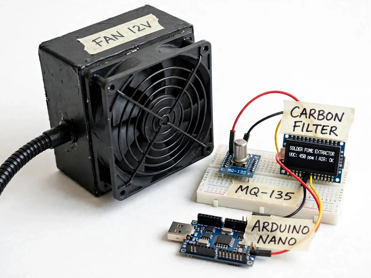
The Solder Fume Extractor with Air Quality Sensing and Variable Fan Speed is a bench tool that answers a problem every electronics student knows: the sting of flux smoke drifting straight into the face, because rosin and no-clean flux release a visible plume of fine particulates and volatile compounds right at the iron tip. Open windows and desk fans only push the plume around the room, plain always-on extractors waste filter life and make constant noise, and none of them tell the student whether the air is actually clean or the filter already saturated. This extractor pulls fumes through a replaceable activated-carbon cartridge with a 120 mm fan, while an MQ-135 sensor samples the exhaust stream and an Arduino Nano maps the reading to automatic PWM fan speed — so the fan works only as hard as the fumes demand, with a live 0–100 air-quality index on an OLED display.
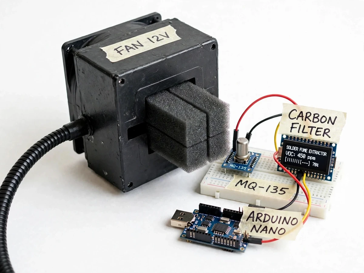
A 120 mm brushless DC fan draws fume-laden air through a replaceable activated-carbon foam cartridge in a square housing, trapping particulates and flux odor as cleaned air exits the back. An MQ-135 gas sensor mounted in the exhaust stream samples the extracted air continuously, and an Arduino Nano converts the sensor's analog voltage into a 0–100 air-quality index shown on an OLED display with fan speed and mode. In auto mode the Nano maps the index to a PWM duty cycle driving the fan through a MOSFET, so airflow ramps up when soldering starts and settles when the air clears. A flexible gooseneck duct positions the intake near the iron, keeping the breathing zone clear without a bulky fume hood.
SnO2 gas sensor in the exhaust stream. Senses VOCs from flux smoke.
Follow the working sequence
How it works
Fume-laden air enters through the gooseneck duct positioned near the soldering iron, passes through the activated-carbon foam cartridge where particulates and flux odor are trapped, and is pushed out the back by the 120 mm fan. The MQ-135 sensor sits in this exhaust stream and its tin-dioxide sensing layer reacts to the volatile compounds in the flux smoke: in clean air the layer holds a high resistance, and as fume concentration rises the resistance falls. The Arduino Nano reads the sensor's analog voltage, converts it to a 0–100 air-quality index, and in auto mode maps that index to a PWM duty cycle that drives the fan through an N-channel MOSFET. A small OLED display continuously shows the index, fan duty percentage and operating mode, while a potentiometer provides manual speed control and a buzzer warns when the index crosses its alert threshold.
- The gooseneck duct is positioned a few centimetres from the soldering iron tip, placing the intake where the flux plume rises.
- The 120 mm brushless DC fan pulls room air and fume through the duct and pushes it through the activated-carbon foam cartridge, which traps particulates and adsorbs flux odor.
- The MQ-135 gas sensor, mounted downstream of the filter in the exhaust stream, samples the extracted air; its SnO2 sensing layer drops in resistance as VOC concentration rises.
- The Arduino Nano reads the sensor's analog output every second and converts it to a smoothed 0–100 air-quality index.
- In auto mode, the Nano maps the index to a PWM duty cycle (0–100%) and drives the fan through an IRF540N MOSFET, so airflow follows fume levels automatically.
- In manual mode, a panel potentiometer sets the duty cycle directly, bypassing the sensor mapping.
- The OLED display updates continuously with the air-quality index, fan duty cycle and active mode; the buzzer and LED alert when the index exceeds the configured threshold.
Tech stack:
- Arduino Nano (ATmega328P) · Arduino IDE
- MQ-135 gas/VOC sensor module
- 120 mm 12 V brushless DC fan
- IRF540N MOSFET PWM fan driver
- 0.96 in OLED display (SSD1306 · I2C)
- Activated-carbon foam filter cartridge
- Gooseneck duct positioning arm
- 12 V DC bench power adapter
| Parameter | Value |
|---|---|
| Fan | 120 mm × 120 mm × 25 mm brushless DC (typical) |
| Fan supply | 12 V DC |
| Filter | Activated-carbon foam cartridge, approximately 115 mm × 115 mm, slide-in replaceable |
| Gas sensor | MQ-135, SnO2 semiconductor type (datasheet) |
| Sensor detection range | 10–1000 ppm benzene · 10–300 ppm NH3 (datasheet values) |
| Sensor supply | 5 V DC circuit voltage (datasheet) |
| Sensor heater | ≤ 950 mW heating consumption (datasheet) |
| Sensor preheat time | Over 48 hours for stable readings (datasheet) |
| Controller | Arduino Nano, ATmega328P, 16 MHz, 5 V logic |
| Display | 0.96 in OLED, 128 × 64 pixels, I2C |
| Fan control | PWM 0–100% duty cycle via N-channel MOSFET |
| Operating modes | Auto (sensor-mapped) and Manual (potentiometer) |
| Positioning duct | Flexible gooseneck, approximately 30 cm |
| Enclosure | Square housing, approximately 140 mm × 140 mm × 120 mm |
Project features
The extractor is defined by four capabilities working together: sensor-driven fan speed, a replaceable filter cartridge, a live air-quality display, and a manual override mode. The MQ-135 gas sensor continuously samples the exhaust stream and the Arduino Nano translates its reading into a 0–100 air-quality index, so the fan responds to real fume levels instead of running blind at full speed — saving filter life and cutting noise. Air passes through a slide-in activated-carbon foam cartridge that traps particulates and flux odor and swaps out in seconds when saturated. A 0.96-inch OLED display shows the air-quality index, current fan duty cycle and operating mode at a glance, and a manual mode with a panel potentiometer gives the user direct control whenever a fixed speed is preferred. The result is a bench tool that works only as hard as the job demands.
- [Sensor-driven automatic fan speed] The MQ-135 reading is converted to a 0–100 air-quality index, which the Arduino maps to a PWM duty cycle driving the fan through a MOSFET. The fan idles quietly in clean air and ramps up automatically as fume concentration rises.
- [Replaceable activated-carbon filter cartridge] A foam cartridge slides into a slot in the housing directly behind the fan grille. It traps solder particulates and flux odor, and lifts out for replacement when saturated — no tools needed.
- [Live air-quality and fan-speed display] A 0.96-inch OLED shows the air-quality index, fan duty cycle as a percentage, and the active mode (AUTO/MANUAL). The builder sees exactly how the system is responding at all times.
- [Manual speed mode with potentiometer] A panel potentiometer lets the user set a fixed fan speed directly. A mode switch toggles between automatic sensor control and manual control instantly.
- [High fume-level alert] A buzzer and indicator LED activate when the air-quality index crosses a configurable threshold, warning the user before fume levels climb further.
- [Flexible positioning duct] A gooseneck duct on the intake side bends to hold the extraction point close to the soldering iron tip, and stays where it is put.
- [Single-supply bench operation] The unit runs from one 12 V DC adapter; an onboard regulator supplies the 5 V rail for the controller, sensor and display.
What is included
- Working bench solder-fume extractor prototype (fan unit, filter cartridge, sensor, controller, display)
- Arduino firmware source code with auto/manual modes and display routines
- Circuit and wiring documentation with connection diagrams
- Complete component list with specifications
- Setup and calibration instructions
- Project report PDF (background, design, methodology, results)
- PPT presentation for final review
- Viva Q&A preparation document (sensors, PWM, MOSFET switching, air-quality indexing)
Limitations & prerequisites
- The MQ-135 responds to many gases (NH3, benzene, smoke, alcohol vapor) and cannot distinguish solder flux fumes from other VOCs — the index is a relative air-quality indicator, not a calibrated ppm measurement of any single gas.
- The sensor needs over 48 hours of preheat (datasheet) before its readings stabilize; measurements taken in the first day or two after power-on drift noticeably.
- The builder note from the bench build: the MQ-135 must sit downstream of the filter, in the exhaust stream — mounting it at the intake saturates the sensing layer with the raw fume plume and is the single most common cause of false high readings in student builds.
- Filter life is component-dependent (soldering hours, flux type); no measured replacement interval is claimed — the rising fan duty and falling air quality on the display are the practical replacement signal.
- Extraction effectiveness falls with distance from the iron tip; the design target is an intake position within approximately 10–15 cm of the tip.
- This is a bench extraction aid, not a certified fume hood — it reduces breathing-zone exposure but the bench should still be in a ventilated room.
- The MQ-135 is temperature and humidity sensitive, so the alert threshold must be calibrated in the room where the unit will be used.
- Fan airflow varies with filter loading and the exact fan model used; no measured CFM figure is claimed.
Frequently Asked Questions
How does the MQ-135 sensor measure solder fume levels?
The MQ-135 carries a tin-dioxide (SnO2) sensing layer kept at working temperature by an internal heater; in clean air this layer holds a high resistance, and when volatile compounds from flux smoke reach it, the resistance falls. The Arduino reads the resulting analog voltage every second and converts it into a smoothed 0–100 air-quality index on the OLED. Because the sensor reacts to many gases, the index is a relative indicator of fume load rather than a calibrated ppm reading of one specific gas.
Is this project suitable for a final-year project?
Yes — for Electronics, Electrical and Instrumentation programs it is a strong fit. It demonstrates sensor interfacing, analog signal conditioning, PWM motor control through a MOSFET, closed-loop control logic, regulated power distribution, and display interfacing in one bench-buildable student system. The working prototype, the visible air-quality feedback loop, and the honest calibration discussion give the student concrete material to demonstrate, explain and defend in the viva.
What power supply does the extractor need?
A single 12 V DC adapter powers the whole unit. The 120 mm fan runs directly from the 12 V rail, while a small onboard regulator derives the 5 V rail for the Arduino Nano, MQ-135 sensor and OLED display. The typical wall adapter is rated 12 V at 2 A, which comfortably covers the fan, the sensor heater and the control electronics together.
Can the fan speed be controlled manually?
Yes — a panel potentiometer sets the fan duty cycle directly in manual mode, bypassing the sensor mapping entirely. A mode switch on the panel toggles between automatic sensor-driven control and manual control at any time without restarting the unit. The OLED always shows which mode is active along with the current duty cycle percentage, so there is never any doubt about what the fan is doing.
How often does the carbon filter need replacing?
Filter life depends on soldering hours and flux type, so no fixed interval is claimed. The practical signal is on the display: when the fan runs at high duty in auto mode yet the air-quality index no longer falls after soldering stops, the cartridge is saturated. The cartridge slides out of its slot and a fresh foam cartridge drops in, with no tools required.
Does the extractor need Wi-Fi or internet?
No — every function runs fully offline on the bench with no network connection at all. Sensing, fan control, the display and the alert all execute locally on the Arduino Nano, so there is nothing to configure and nothing that can drop out mid-session. There is no cloud dashboard and no companion app, which keeps the build simple, the firmware easy to explain, and the bill of materials low.
Components & software requirements
- Arduino Nano (ATmega328P) · Arduino IDE
- MQ-135 gas/VOC sensor module
- 120 mm 12 V brushless DC fan
- IRF540N MOSFET PWM fan driver
- 0.96 in OLED display (SSD1306 · I2C)
- Activated-carbon foam filter cartridge
- Gooseneck duct positioning arm
- 12 V DC bench power adapter
Delivery information
Built-to-order project. Delivery timeline is shared after order confirmation based on current queue.
Support terms
Complete documentation, setup guide, and viva preparation included. Support for setup and explanation provided.
Download free synopsis (PDF)
Enter your name and WhatsApp number — the synopsis PDF downloads immediately. We may send occasional project updates on WhatsApp; no spam.