
More project photos (2)
The problem
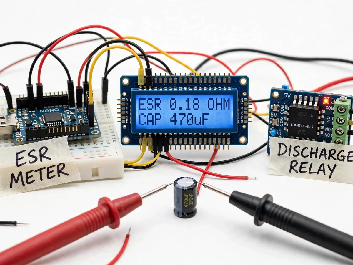
An in-circuit capacitor ESR meter is a bench diagnostic tool that identifies failing electrolytic capacitors without removing them from the board. Many failures blamed on a "dead power supply" or glitching motherboard trace back to electrolytics whose equivalent series resistance has quietly climbed with age and heat: capacitance still reads fine, but risen ESR causes excess ripple, overheating, and board-level failure. A standard multimeter cannot catch this — its resistance mode applies DC, measuring only megohm-range leakage resistance, not the AC series resistance that matters at operating frequencies. Desoldering every suspect capacitor is slow and risks lifting pads on dense multilayer boards. This project closes that gap with an Arduino Nano–based meter that injects a small 100 kHz AC test signal — the industry-standard ESR test frequency — through hand probes and reads the resistance directly in ohms, giving a fast good-or-bad verdict while the capacitor stays soldered in place.
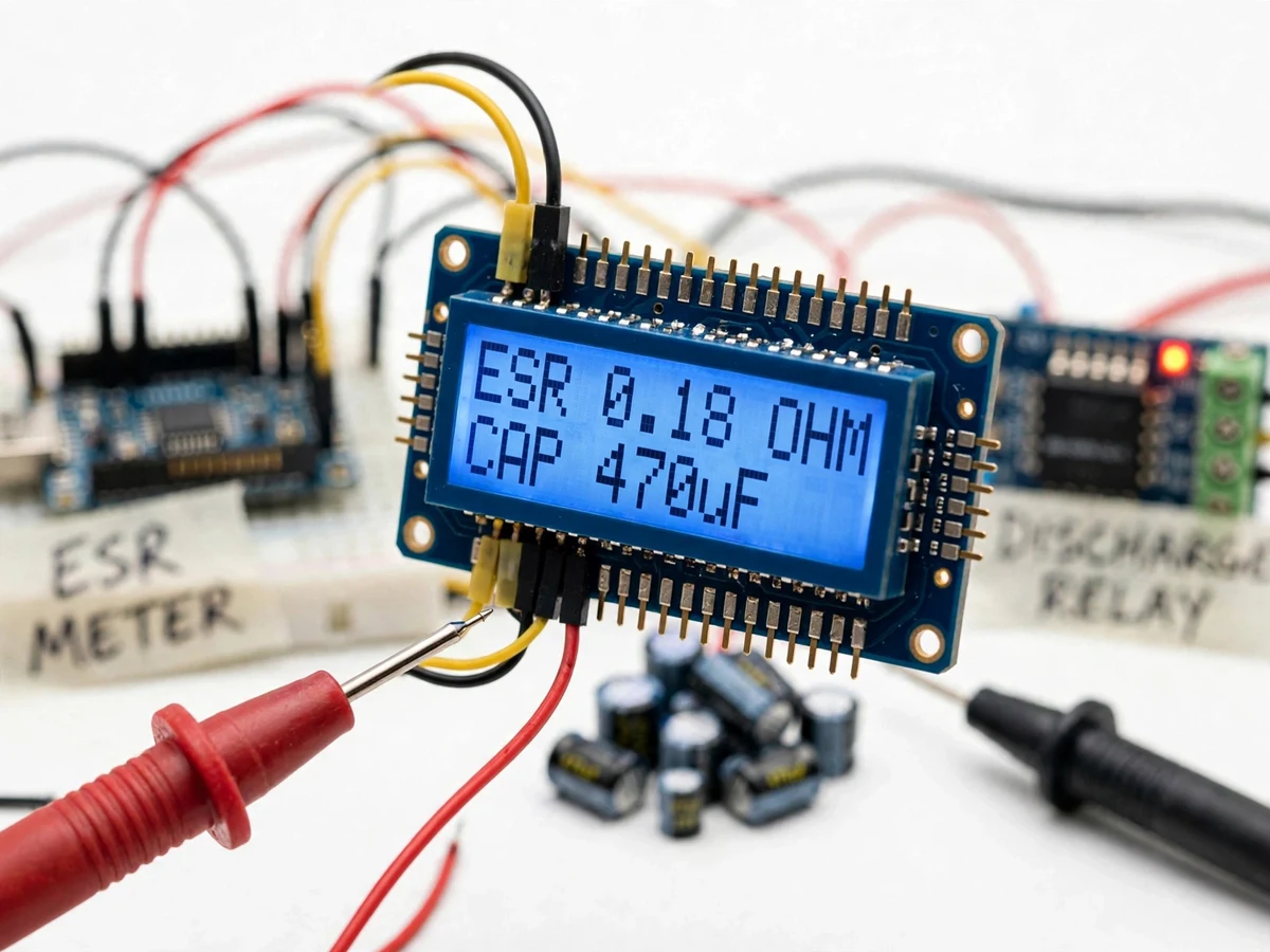
Touch the capacitor and carry the AC test signal.
Follow the working sequence
How it works
The in-circuit capacitor ESR meter works in a strict sequence — sense DC, discharge, then test — protecting the delicate sense amplifier. The Arduino Nano first reads the capacitor's DC voltage through a divider. Above about 0.5 V, a 5 V relay routes the capacitor through a 100 Ω, 10 W wirewound resistor, draining it while the LCD shows DISCHARGING; the relay releases only below the threshold, and voltages above the 63 V rating trigger an overvoltage lockout instead. Then the Nano starts its ~100 kHz square-wave test signal, current-limited into the probes. At 100 kHz the capacitor's reactance is negligible, so the AC voltage across it is essentially the drop across its ESR. An op-amp amplifies this millivolt-level signal roughly twentyfold, a peak detector converts it to DC, and the ATmega328P's 10-bit ADC digitizes it; firmware subtracts the shorted-probe zero, applies the 1 Ω reference calibration, and displays the ESR in ohms with a verdict.
- The probes touch the capacitor under test; the firmware first measures the DC voltage across the probes through a resistive divider — no test signal is active yet.
- If the DC voltage exceeds roughly 0.5 V, the discharge relay engages, draining the capacitor through the 100 Ω, 10 W resistor while the LCD shows DISCHARGING; if it exceeds the 63 V design rating, the meter locks out and shows an overvoltage warning instead.
- Once the residual voltage falls below the threshold, the relay releases and the Nano's timer starts the ~100 kHz square-wave test signal, current-limited into the probes.
- At 100 kHz the capacitor's reactance collapses to milliohms, so the AC voltage across the probes is almost entirely the voltage drop across the ESR; a coupling capacitor blocks any residual DC before the sense stage.
- An LM358 op-amp amplifies the millivolt-level AC signal by roughly 20× (design target), and a diode peak detector converts it to a DC level.
- The ATmega328P's 10-bit ADC samples the detector output with 64× firmware averaging to suppress noise.
- Firmware subtracts the stored shorted-probe zero, applies the 1 Ω span calibration, computes ESR from the amplified voltage and the known test current, and shows the result in ohms with a GOOD / FAIR / BAD verdict on the LCD.
Builder's note (design calculation): the discharge relay must engage before the test signal is ever generated, because a charged capacitor would impress its full DC voltage on the sense amplifier's input — saturating it and risking damage — while also corrupting the millivolt-level ESR measurement. The discharge resistor is sized from the capacitor's stored energy, E = ½CV². For the largest capacitor this meter handles, 4700 µF at the 63 V design rating: E = ½ × 0.0047 × 63² ≈ 9.3 J. Drained through a 100 Ω resistor, the peak dissipation is V²/R = 63²/100 ≈ 40 W, decaying exponentially with time constant τ = RC ≈ 0.47 s; the capacitor is effectively drained in about five time constants (~2.4 s), so the average dissipation is roughly 9.3 J / 2.4 s ≈ 4 W. A 10 W ceramic wirewound resistor therefore handles even the worst case with comfortable margin.
Tech stack:
- Arduino Nano (ATmega328P, 10-bit ADC)
- Arduino IDE (C++ firmware)
- ~100 kHz square-wave test oscillator (timer-driven)
- LM358 op-amp · diode peak detector
- 5 V relay discharge module · 100 Ω 10 W resistor
- 16x2 character LCD (HD44780, 5 V)
- Resistive divider probe-voltage sensing
- 5 V USB / 9 V battery power
| Parameter | Value |
|---|---|
| Controller | Arduino Nano (ATmega328P, 10-bit ADC — Microchip datasheet) |
| Test signal | ~100 kHz square wave (design target) |
| Probe test voltage | ~0.5 V peak-to-peak (design target) |
| ESR measurement range | 10 mΩ – 30 Ω (design target) |
| Display resolution | 0.01 Ω (design target) |
| Accuracy | ±10% of reading ±2 digits (design target, after zero/span calibration) |
| Capacitor range | 1 µF – 4700 µF electrolytic (design target) |
| Discharge rating | ≤ 63 VDC (design rating) |
| Discharge resistor | 100 Ω, 10 W ceramic wirewound (design value) |
| Sense amplifier gain | ~20× (design target) |
| Display | 16 × 2 character LCD, 5 V supply (datasheet) |
| Power | 5 V USB or 9 V battery (expected) |
Project features
The in-circuit capacitor ESR meter combines four capabilities for a genuine bench instrument: a ~100 kHz AC test signal, a relay-driven auto-discharge stage, a direct ohms readout with a good/fair/bad verdict, and a two-point calibration routine. The 100 kHz test signal is the heart of the design — at this frequency the capacitive reactance of a typical electrolytic collapses to milliohms (a 100 µF capacitor presents just 0.016 Ω of reactance, from Xc = 1/(2πfC)), so nearly all of the measured AC voltage drop is the ESR itself, the quantity capacitor datasheets specify at 100 kHz. The auto-discharge stage answers the danger of probing charged capacitors: the firmware senses residual DC on the probes first and, before any test signal is generated, closes a relay that bleeds the capacitor through a power resistor sized from E = ½CV². The LCD then reports the ESR in ohms with a verdict, and a zero-plus-span calibration keeps readings honest.
- [100 kHz AC test signal] A timer-driven ~100 kHz square wave, current-limited through a resistor into the probes. At 100 kHz a 100 µF capacitor's reactance is only about 0.016 Ω, so the measured AC voltage drop is dominated by the series resistance rather than the capacitance.
- [Auto-discharge relay protection] Before every measurement the firmware reads the DC voltage on the probes; if residual charge above roughly 0.5 V is found, a 5 V relay shunts the capacitor through a 100 Ω, 10 W wirewound resistor until it is drained. The test signal is never generated until the probes are safe.
- [Overvoltage lockout] If the sensed capacitor voltage exceeds the discharge circuit's 63 VDC design rating, the meter refuses the measurement and displays an overvoltage warning instead of attempting a discharge it cannot safely handle.
- [Direct ohms readout with verdict] The 16x2 LCD shows the measured ESR in ohms alongside a GOOD / FAIR / BAD verdict referenced to typical electrolytic ESR ranges for the dialed capacitance value.
- [Zero and span calibration] A shorted-probe reading zeroes out probe and wiring resistance, and a 1 Ω, 1% film reference resistor sets the span, so readings stay honest as probes wear.
- [In-circuit screening] The small test signal (design target ~0.5 V peak-to-peak at the probes) is kept below typical silicon junction turn-on, so surrounding semiconductors stay off during the brief measurement.
- [Bench-portable build] Powered from 5 V USB or a 9 V battery, with the whole instrument — Nano, LCD, relay module and probes — in one hand-carried unit.
What is included
- Working, calibrated ESR meter prototype (Arduino Nano, 16x2 LCD, discharge relay module, test probes)
- Complete firmware source code (Arduino C++)
- Circuit schematic and wiring documentation
- Component list with part values and ratings
- Step-by-step test and calibration procedure (shorted-probe zero + 1 Ω span)
- Project report PDF (background, ESR theory, design, methodology, results)
- PPT presentation for final review
- Viva Q&A preparation document (impedance, op-amps, ADC, safety interlocking)
Limitations & prerequisites
- In-circuit readings are a screening step, not a lab measurement: parallel low-impedance paths on the board appear in parallel with the capacitor under test and can make a failing capacitor read lower than it truly is. Lifting one leg gives the definitive reading.
- Charged capacitors are dangerous: the discharge circuit is rated to 63 VDC maximum — never probe mains filter capacitors or any capacitor charged above this rating. The overvoltage lockout is a backup, not a substitute for care.
- Designed for 1 µF – 4700 µF electrolytic capacitors. Below roughly 0.47 µF the 100 kHz capacitive reactance (~3.4 Ω at 0.47 µF) contaminates the reading, and most film/ceramic ESR values sit below the 10 mΩ resolution floor anyway.
- ESR is frequency-dependent: the reading is valid at the meter's ~100 kHz test frequency and is comparable to datasheet 100 kHz specifications, not to 120 Hz ripple-current ratings.
- Accuracy is a design target (±10% of reading ±2 digits after zero/span calibration), not a lab-calibrated claim; probe contact resistance and lead inductance affect the lowest readings.
- The meter assumes the circuit under test is powered OFF — it cannot verify this itself. Probing a live circuit will damage the meter and endanger the operator.
- It is a student prototype, not a calibrated lab instrument; readings should be cross-checked against a known reference resistor during demonstrations.
Frequently Asked Questions
Why measure ESR at 100 kHz instead of using a multimeter's resistance mode?
A multimeter's resistance mode applies DC, which measures only the capacitor's leakage resistance — typically megohms — and says nothing about ESR. ESR is an AC parameter, and 100 kHz is the industry-standard test frequency: at 100 kHz a 100 µF capacitor's reactance is only about 0.016 Ω, so practically the entire AC voltage drop across it is the series resistance, which this meter reads directly.
How does the auto-discharge protection work?
Before every measurement the firmware reads the DC voltage across the probes. If it finds residual charge above roughly 0.5 V, it closes a relay that connects the capacitor to a 100 Ω, 10 W resistor until the voltage falls below the threshold — the test signal is only generated afterwards. Voltages above the 63 V design rating trigger an overvoltage lockout instead.
Can it really measure capacitors without desoldering them?
For screening, yes: the small test signal stays below typical silicon junction turn-on, so surrounding semiconductors remain off and you get a fast good-or-bad reading in place. But the physics is honest — parallel low-resistance paths on the board appear in parallel with the capacitor and can make a bad one read lower than it is. Treat the in-circuit reading as a screen; lifting one leg gives the definitive number.
Which capacitors can it measure?
The design targets 1 µF to 4700 µF electrolytic capacitors — the family where rising ESR is the dominant failure mode — with a reading range of about 10 mΩ to 30 Ω. Below roughly 0.47 µF the capacitive reactance at 100 kHz (about 3.4 Ω at 0.47 µF) starts to contaminate the reading, so small ceramic and film capacitors are out of scope.
Is this project suitable for a final-year project?
Yes — for Electronics & Telecommunication, Electronics and Electrical Engineering programs. It demonstrates AC impedance concepts, analog signal conditioning with an op-amp and peak detector, ADC interfacing on the ATmega328P, timer-generated waveforms, relay-based safety interlocking, and firmware built around a genuine protection sequence — all defensible in a viva.
Components & software requirements
- Arduino Nano (ATmega328P, 10-bit ADC)
- Arduino IDE (C++ firmware)
- ~100 kHz square-wave test oscillator (timer-driven)
- LM358 op-amp · diode peak detector
- 5 V relay discharge module · 100 Ω 10 W resistor
- 16x2 character LCD (HD44780, 5 V)
- Resistive divider probe-voltage sensing
- 5 V USB / 9 V battery power
Delivery information
Built-to-order project. Delivery timeline is shared after order confirmation based on current queue.
Support terms
Complete documentation, setup guide, and viva preparation included. Support for setup and explanation provided.
Download free synopsis (PDF)
Enter your name and WhatsApp number — the synopsis PDF downloads immediately. We may send occasional project updates on WhatsApp; no spam.