
More project photos (3)
The problem
Cheap digital thermometers built on thermistors or IC sensors such as the LM35 drift with supply voltage and lose accuracy away from room temperature, and most student thermometer builds read a sensor voltage with the Arduino's own ADC — a chain where reference-voltage error, sensor self-heating and curve-fitting each add unknown error. Industrial measurement avoids this with platinum RTDs: a PT100 element follows the IEC 60751 resistance–temperature curve to a fraction of a degree and stays stable for years. This project brings that professional chain to student scale — a class-B PT100 probe, the MAX31865 RTD-to-digital converter (15-bit resolution, SPI interface, 2/3/4-wire support per its datasheet) and an Arduino Nano that linearizes each reading with the Callendar–Van Dusen equation and shows it on a 16x2 LCD. A buyer-run two-point calibration (ice bath at 0 °C, boiling water at 100 °C) trims out probe interchange error, targeting ±0.5 °C over 0–100 °C as a design target.
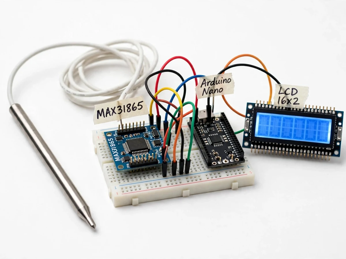
3-wire platinum RTD probe; its resistance is 100 ohm at 0 C and rises 3850 ppm per degree C.
Follow the working sequence
How it works
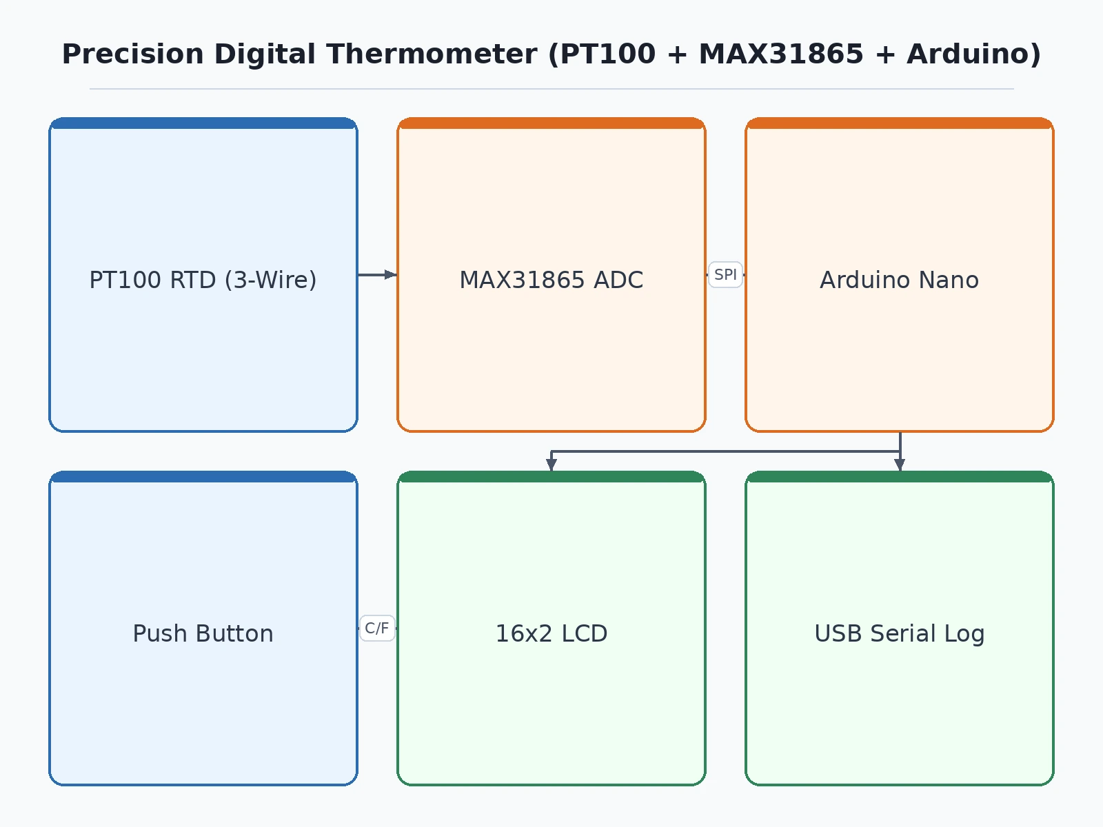
- The PT100 probe's platinum element changes resistance with temperature — 100 Ω at 0 °C, rising at 3850 ppm/°C per IEC 60751.
- The MAX31865 drives a small excitation current through the probe and measures its resistance ratiometrically against a 400 Ω, 0.1% reference resistor.
- The chip's 15-bit delta-sigma ADC digitizes the resistance ratio while its fault block checks for open or shorted probe leads.
- The Arduino Nano reads the result over SPI and applies the Callendar–Van Dusen equation to convert resistance into temperature.
- The buyer-run two-point calibration (ice bath, boiling water) corrects probe interchange error; corrections are stored in EEPROM.
- The corrected temperature is shown on the 16x2 LCD at 0.1 °C resolution and streamed over USB serial once per second.
- Min/max values are tracked in memory and recalled on demand with a button press.
Tech stack:
- Arduino Nano (ATmega328P)
- MAX31865 RTD-to-digital converter
- PT100 RTD probe, class B, 3-wire
- Arduino IDE (C/C++ firmware)
- 16x2 LCD (HD44780 controller)
- SPI communication
- Callendar–Van Dusen equation
- USB serial logging
| Parameter | Value |
|---|---|
| RTD sensor | PT100, 100 Ω at 0 °C (datasheet value, IEC 60751) |
| Temperature coefficient | 3850 ppm/°C (datasheet value, IEC 60751) |
| Probe range | −50 °C to +250 °C (datasheet value, typical class-B thin-film probe) |
| Probe tolerance | ±(0.30 + 0.005·|t|) °C (datasheet value, IEC 60751 class B) |
| Converter IC | MAX31865 RTD-to-digital converter (datasheet) |
| ADC resolution | 15-bit, nominal 0.03125 °C per LSB (datasheet value; varies with RTD nonlinearity) |
| Reference resistor | 400 Ω, 0.1% (datasheet-recommended value for PT100) |
| RTD wiring | 2-, 3- and 4-wire supported (datasheet); 3-wire with lead compensation (implemented) |
| Interface | SPI, up to 5 MHz (datasheet value) |
| Display resolution | 0.1 °C (design target) |
| Accuracy | ±0.5 °C over 0–100 °C (design target, after buyer two-point calibration) |
| Power supply | 5 V via USB or 7–12 V barrel jack (design target) |
Project features
- [15-bit RTD-to-digital conversion] The MAX31865 converts PT100 resistance ratiometrically against a 400 Ω reference with 15-bit resolution (nominal 0.03125 °C per LSB per datasheet), so the reading never depends on the Arduino's unstable ADC reference.
- [3-wire lead-resistance compensation] The PT100 is wired in 3-wire configuration; the input stage cancels the matched lead-wire resistance that would otherwise add several tenths of a degree of error on longer probe cables.
- [Callendar–Van Dusen linearization] Firmware converts measured resistance to temperature with the IEC 60751 Callendar–Van Dusen relation rather than a straight-line fit, keeping the reading accurate across the full probe range.
- [0.1 °C display with °C/°F toggle] Readings appear on a 16x2 LCD at 0.1 °C resolution, and a push button switches between Celsius and Fahrenheit without restarting the unit.
- [Two-point calibration mode] A guided routine walks the buyer through an ice-bath (0 °C) and boiling-water (100 °C) measurement and stores offset and gain corrections in EEPROM; the full procedure is documented step by step.
- [Min/max hold] The firmware tracks the minimum and maximum temperature seen since reset and recalls them on demand — handy for oven and environmental monitoring demonstrations.
- [Open/short fault detection] The MAX31865's integrated fault detection flags a disconnected, shorted or out-of-range probe on the display instead of showing a plausible-looking wrong number.
- [USB serial data output] Every reading is streamed as plain text over USB serial once per second for PC logging or plotting; SD-card data logging is available as an optional customization.
What is included
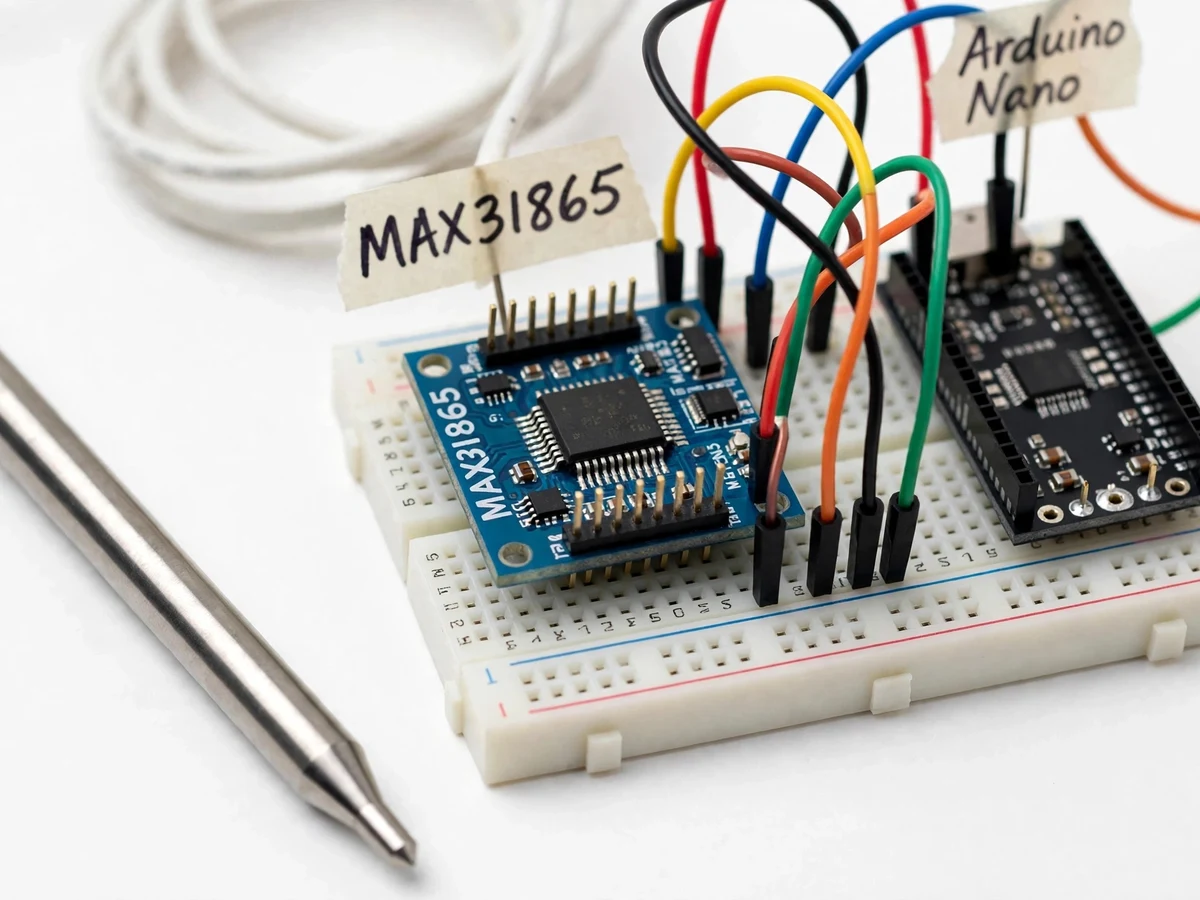
- Assembled and tested working prototype (Arduino Nano, MAX31865 breakout, PT100 probe, 16x2 LCD, wiring)
- Complete firmware source code (Arduino C/C++, commented)
- Wiring diagram and connection documentation
- Two-point calibration guide (ice bath / boiling water procedure with altitude note)
- Component list with part numbers and sourcing notes
- Project abstract PDF
- Project report PDF (background, RTD theory, methodology, build procedure)
- PPT presentation for final review
- Viva Q&A preparation document (RTD theory, SPI, linearization, calibration)
Limitations & prerequisites
- Final accuracy depends on the probe's class-B tolerance (±(0.30 + 0.005·|t|) °C per IEC 60751) and on how carefully the buyer performs the two-point calibration; this is not a certified instrument and ships without a calibration certificate.
- RTD excitation current causes slight self-heating (typically tenths of a degree in still air); the firmware uses one-shot conversions to keep this effect small.
- The boiling-point calibration reference assumes 100 °C, which holds only at sea-level atmospheric pressure — at altitude the correction table must be adjusted.
- The MAX31865 reports resistance digitally and temperature conversion runs in firmware, so switching RTD types (e.g. PT1000) needs a code change.
- Display resolution (0.1 °C) is finer than the accuracy (±0.5 °C design target) — the extra digit is for trend observation, not measurement confidence.
- Response time is set by the probe's thermal mass: typically a few seconds in water and longer in still air (approximate).
- Wired, USB-powered instrument with no wireless readout or cloud logging in the base build (both available as optional customizations).
Frequently Asked Questions
Is this project suitable for a final-year project?
Yes — for Electronics & Telecommunication and Electrical programs. It demonstrates RTD sensor theory, SPI communication, ratiometric resistance measurement, Callendar–Van Dusen linearization in firmware and a real two-point calibration procedure, which together make strong, defensible viva material for instrumentation or embedded-systems topics.
Why a PT100 and MAX31865 instead of a thermistor or LM35?
A PT100's resistance–temperature curve is defined by the IEC 60751 standard and stays stable for years, while thermistor curves vary part to part and drift. The MAX31865 adds 15-bit ratiometric conversion, so supply-voltage wobble cannot corrupt the reading the way it does with the Arduino's own ADC. That is why process industries standardize on RTDs.
How accurate is it really?
The honest answer has two parts: the chip side is specified at 0.5 °C maximum total error (datasheet), but the class-B probe itself carries ±(0.30 + 0.005·|t|) °C tolerance (IEC 60751). The ±0.5 °C design target over 0–100 °C assumes the buyer performs the documented two-point calibration; uncalibrated, probe interchange error dominates.
What does the two-point calibration involve?
You measure a well-stirred ice bath (true 0 °C) and vigorously boiling water (100 °C at sea level), then the calibration routine stores offset and gain corrections in EEPROM. The guide documents water purity, stirring, immersion depth and the altitude correction for the boiling point.
Can it log data or send readings wirelessly?
The base build streams plain-text readings over USB serial once per second, which a PC can log or plot. SD-card logging and Bluetooth or Wi-Fi readout are not in the base build — they are available as optional customizations, and adding Wi-Fi would move the project into IoT territory.
What power supply does it need?
5 V over USB is enough for bench use and calibration, and a 7–12 V barrel-jack input supports standalone operation. Total current draw stays well within typical USB limits as a design target.
Components & software requirements
- Arduino Nano (ATmega328P)
- MAX31865 RTD-to-digital converter
- PT100 RTD probe, class B, 3-wire
- Arduino IDE (C/C++ firmware)
- 16x2 LCD (HD44780 controller)
- SPI communication
- Callendar–Van Dusen equation
- USB serial logging
Delivery information
Built-to-order project. Delivery timeline is shared after order confirmation based on current queue.
Support terms
Complete documentation, setup guide, and viva preparation included. Support for setup and explanation provided.
Download free synopsis (PDF)
Enter your name and email — the synopsis PDF downloads immediately. We may send occasional project updates; no spam, unsubscribe anytime.