
More project photos (2)
The problem
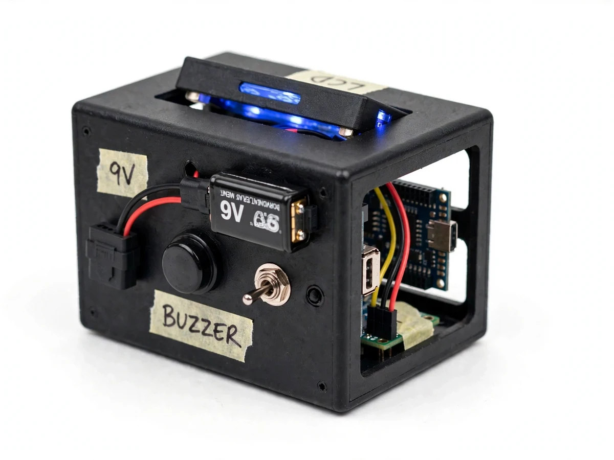
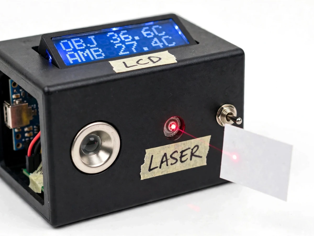
Every object above absolute zero radiates infrared energy, and that radiation carries its surface temperature — if you can catch and decode it. The Melexis MLX90614 does exactly that inside a small TO-39 metal can: a thermopile senses the incoming IR, an on-chip DSP applies the factory calibration, and the result comes out over a digital SMBus/I2C link. This project turns that sensor into a complete handheld instrument. An Arduino Nano polls the MLX90614 for object and ambient temperature, shows both on a 16x2 LCD, and drives a low-power red laser diode that marks the spot being measured. A piezo buzzer sounds when the reading crosses an adjustable threshold defaulting to 37.5°C, which suits fever-screening demonstrations, quick HVAC surface checks and hunting hot spots on electronics. A 9 V battery with a panel switch keeps the unit portable. The sensor is factory calibrated for emissivity 1.0 with ±0.5°C accuracy near room temperature (datasheet values) — every performance figure on this page traces to the datasheet, and nothing is claimed as measured until the calibration run is executed for the order.
Thermopile senses infrared from the surface inside its 90 degree field of view; on-chip DSP outputs the object temperature.
Follow the working sequence
How it works
- The MLX90614's thermopile detects infrared radiation from the surface inside its field of view; the on-chip DSP converts it to a digital object temperature, factory calibrated over −70°C to +380°C.
- The Arduino Nano polls the sensor over SMBus-compatible I2C (default address 0x5A) roughly every 0.5 s, reading both the object temperature and the sensor die's ambient temperature at 0.02°C digital resolution (datasheet value).
- Firmware applies the emissivity correction for the selected surface (default 1.0, adjustable 0.1–1.0) and formats both values for display.
- The 16x2 LCD shows the object temperature on line 1 and the ambient temperature on line 2, with 0.1°C display resolution (design target).
- The laser diode, mounted parallel to the sensor axis, puts a red dot at the centre of the 90° sensing cone so the user sees exactly which spot is being measured.
- If the object temperature exceeds the configured threshold (37.5°C default), the Nano drives the piezo buzzer; the threshold is a firmware constant the buyer can change.
- A 9 V battery feeds the Nano's on-board 5 V regulator; the panel switch isolates the battery when the unit is off, and the MLX90614 itself draws under 2 mA (datasheet value).
Tech stack:
- Arduino Nano (ATmega328P)
- Melexis MLX90614 IR temperature sensor (I2C/SMBus)
- Arduino C++ firmware
- 16x2 LCD (HD44780 controller)
- Red laser diode module (650 nm)
- Piezo buzzer, 9 V battery power
- ABS enclosure with perfboard assembly
| Parameter | Value |
|---|---|
| IR sensor | Melexis MLX90614, I2C/SMBus interface (datasheet value) |
| Object temperature range | −70°C to +380°C (datasheet value) |
| Ambient temperature range | −40°C to +125°C (datasheet value) |
| Standard accuracy | ±0.5°C near room temperature (datasheet value) |
| Medical variant accuracy | ±0.2°C near body temperature (datasheet value; special version, on request) |
| Digital resolution | 0.02°C via SMBus (datasheet value) |
| Display resolution | 0.1°C (design target) |
| Field of view | 90° (datasheet value, standard variant) |
| Factory emissivity | 1.0, adjustable 0.1–1.0 (datasheet value) |
| Fever threshold | 37.5°C default, firmware-adjustable (design choice) |
| Measurement distance | 5–15 cm (design target) |
| Display refresh | Approximately 0.5 s (expected) |
| Sensor supply current | Under 2 mA (datasheet value) |
| Battery | 9 V, approximately 5–6 hours continuous use (approximate) |
| Enclosure | Handheld ABS project box, approximately 12 × 8 × 4 cm (approximate) |
Project features
- [Non-contact IR temperature sensing] The MLX90614 measures surface temperature from a distance using emitted infrared radiation, so the unit reads moving parts, hot surfaces and skin without any contact. (implemented)
- [Laser-marked measurement spot] A low-power red laser diode projects a dot at the centre of the sensor's field of view, so there is no guesswork about which spot the reading belongs to. (implemented)
- [Dual temperature display] The 16x2 LCD shows object temperature and ambient temperature side by side, refreshing roughly every half second. (implemented)
- [Configurable fever-threshold alarm] The piezo buzzer sounds when the object reading crosses a threshold that defaults to 37.5°C and can be changed in firmware for other use cases. (implemented; threshold configurable)
- [Battery-powered handheld unit] A 9 V battery and panel-mounted power switch make the unit fully portable for screening demos and field checks. (implemented)
- [Emissivity-compensated readings] Firmware applies a correction for surfaces whose emissivity differs from the sensor's factory calibration of 1.0, set from a small material table in the code. (implemented; setting configurable)
- [Optional reading-hold function] A push-button freezes the current reading on the LCD for note-taking; enabled in firmware on request. (optional)
What is included
- Assembled and tested handheld thermometer unit in enclosure
- Firmware source code (Arduino C++, commented)
- Complete wiring diagram and component list
- Calibration guide (ice-bath and reference-thermometer procedure with datasheet traceability)
- Project report PDF (background, sensor theory, methodology, calibration results)
- PPT presentation for final review
- Viva Q&A preparation document (IR sensing, I2C, emissivity, field of view)
Limitations & prerequisites
- Academic prototype, not certified medical equipment — readings must never be used for clinical diagnosis or any health decision.
- Surface temperature only: it cannot read core or internal body temperature, and shiny or metallic surfaces read low because of low emissivity.
- The ±0.5°C accuracy (datasheet value) holds only in thermal equilibrium — hot electronics behind the sensor or rapid ambient changes degrade it.
- The 90° field of view widens with distance, so the unit is designed for short range (~5–15 cm, design target); aiming matters.
- The laser is a low-power aiming aid only — never point it at eyes or reflective surfaces.
- The 9 V battery gives roughly 5–6 hours of continuous use (approximate); the unit is for indoor lab conditions and is not weatherproof.
Frequently Asked Questions
How accurate is it?
The MLX90614's standard accuracy is ±0.5°C around room temperature, guaranteed only in thermal equilibrium per the Melexis datasheet. A special medical variant offers ±0.2°C near body temperature and can be used on request. Our report documents the calibration run honestly — we never claim a measured figure in advance.
Can it detect fever or be used for medical screening?
It can demonstrate screening-style checks: skin-surface readings above the 37.5°C threshold trigger the buzzer. But it is an academic prototype, not certified medical equipment — it measures skin surface temperature, not core temperature, and its readings must never be treated as clinical data or used for diagnosis.
Why does it need the laser pointer?
The MLX90614 reads a single spot but has no sight of its own — at a distance its 90° field of view covers a wide area. The laser marks the centre of that area so you know which surface the reading belongs to. The laser takes no part in the measurement itself.
How is this different from the contact PT100 thermometer and the MLX90640 thermal camera listed here?
Three different instruments: the PT100 page is a contact thermometer that must touch the target; the MLX90640 page is a 32x24-pixel thermal imaging array that produces a picture; this is a single-point non-contact sensor — cheaper, simpler code, and aimed at spot checks and fever-threshold screening.
Is this project suitable for a final-year project?
Yes — for Electronics, E&TC and Electrical programs. The student works with a real IR sensor over I2C, writes the firmware, designs the threshold logic, calibrates against a reference and packages a working instrument. The report carries full datasheet traceability, which makes the viva discussion technical rather than descriptive.
Components & software requirements
- Arduino Nano (ATmega328P)
- Melexis MLX90614 IR temperature sensor (I2C/SMBus)
- Arduino C++ firmware
- 16x2 LCD (HD44780 controller)
- Red laser diode module (650 nm)
- Piezo buzzer, 9 V battery power
- ABS enclosure with perfboard assembly
Delivery information
Built-to-order project. Delivery timeline is shared after order confirmation based on current queue.
Support terms
Complete documentation, setup guide, and viva preparation included. Support for setup and explanation provided.
Download free synopsis (PDF)
Enter your name and email — the synopsis PDF downloads immediately. We may send occasional project updates; no spam, unsubscribe anytime.