
More project photos (2)
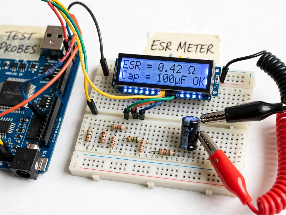
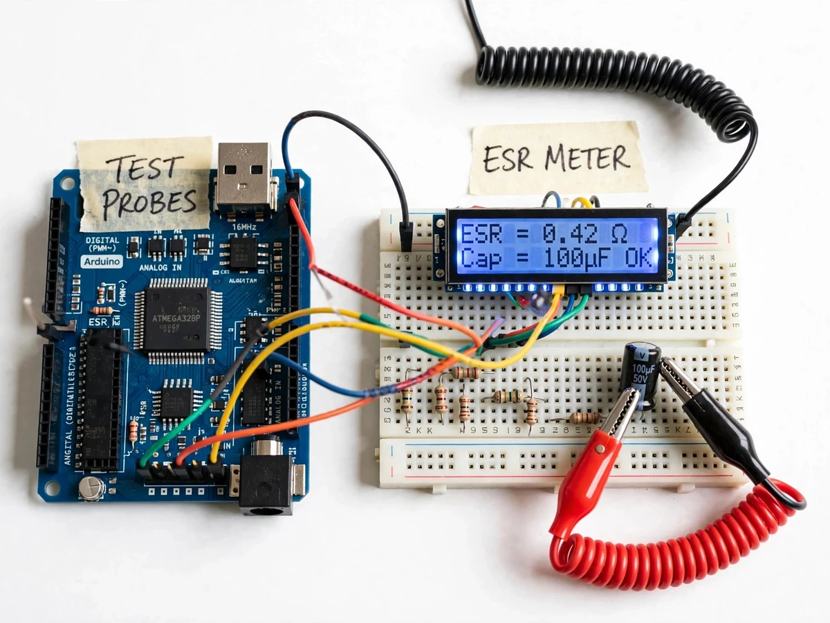
The problem
Electrolytic capacitors are among the most failure-prone components in power supplies and audio equipment, and they rarely fail open or short — they dry out. A capacitor can still read near its rated capacitance on a multimeter while its equivalent series resistance (ESR) has climbed many times over, causing excess ripple, overheating and faults that look like anything but a bad capacitor. The failure mode is invisible to a basic multimeter: you need an ESR measurement. Commercial ESR meters exist but cost more than a student can justify for a repair bench, and ordinary capacitor testers measure capacitance only. This project builds the affordable answer: an Arduino-based ESR meter that fires a short, controlled current pulse through a known precision resistor into the capacitor under test and computes ESR from the resulting voltage step. A 16x2 LCD shows the reading with a good/high judgement against datasheet-typical family values, and a short-probe zero calibration plus a reference-resistor check keep the readings honest. It is genuine electronic instrumentation — measurement theory, ADC interfacing and calibration methodology in one practical bench tool.
How it works
- The red and black alligator probes are clipped across the discharged capacitor under test.
- On the test button press, firmware first discharges the capacitor through a 1 kΩ discharge resistor until the ADC reads below approximately 0.1 V.
- A digital pin drives 5 V through the known precision series resistor into the capacitor; the ADC samples the capacitor-side voltage within microseconds of the pulse edge.
- At the step edge the capacitor behaves as a short, so the measured voltage step ΔV is set by the ESR: firmware computes ESR = ΔV × Rseries / (Vdrive − ΔV), repeating the pulse 16 times (design choice) and averaging to reduce noise.
- The stored short-probe zero offset is subtracted; the corrected ESR is compared against the firmware's datasheet-typical family table and shown on the LCD in ohms with an OK/HIGH hint.
- Firmware then measures the time for the capacitor to charge to ~63% of the drive voltage through the known resistor (τ = R×C) and shows the approximate capacitance alongside.
Tech stack:
- Arduino Uno (ATmega328P, 10-bit ADC, ~4.9 mV per LSB)
- Embedded C++ firmware (Arduino IDE)
- 16x2 LCD (HD44780) with I2C backpack
- Known precision series resistor (10 Ω, 1% metal film, design choice)
- 1 kΩ discharge resistor + push-button test trigger
- Alligator-clip test probes
- EEPROM zero-offset storage + averaging firmware
- Reference ESR table from datasheet-typical values
| Parameter | Value |
|---|---|
| Controller | Arduino Uno, ATmega328P, 10-bit ADC (0–5 V, approximately 4.9 mV/LSB, datasheet) |
| Measurement method | DC-pulse ESR through a known precision series resistor (not an AC bridge) |
| ESR range | Approximately 0.1 Ω to 50 Ω (design target, range-dependent) |
| ESR resolution | Approximately 0.1 Ω on the low range (design target) |
| Capacitance estimate | Approximately 1 µF to 10,000 µF electrolytic (expected; charge-time method) |
| Display | 16x2 LCD (HD44780) with I2C backpack |
| Calibration | Short-probe zero offset in EEPROM + 1 Ω / 10 Ω (1%) reference-resistor check |
| Test leads | Alligator-clip probes, approximately 60 cm leads (expected) |
| Supply | 5 V USB or 9 V battery; current draw approximately 50–80 mA (expected) |
| Judgement table | Datasheet-typical ESR values per capacitor family (OK / HIGH hint) |
Project features
- [One-press ESR measurement] Clip the probes across the capacitor and press the test button — the meter discharges the capacitor, fires the measurement pulse, averages the readings and shows ESR on the LCD. No oscilloscope or manual math needed.
- [DC-pulse ESR method] The capacitor under test is driven with a short current pulse through a known precision series resistor; the Arduino ADC samples the voltage step at the pulse edge, where the capacitor behaves as a short and the step is set by ESR alone: ESR = ΔV × Rseries / (Vdrive − ΔV).
- [LCD readout with good/high judgement] A 16x2 LCD shows the measured ESR in ohms alongside an OK/HIGH hint, judged against a firmware table of datasheet-typical ESR values per capacitor family.
- [Short-probe zero calibration] Shorting the probes runs a zero-calibration that stores the lead and contact resistance offset in EEPROM, subtracted automatically from every measurement.
- [Reference-resistor verification] The kit includes 1 Ω and 10 Ω (1%) reference resistors; a verification mode measures them so the student can confirm the meter's accuracy themselves.
- [Automatic capacitor discharge] Before each test the firmware discharges the capacitor through a discharge resistor until the residual voltage is negligible — a safety habit built into the instrument.
- [Approximate capacitance readout] The same charge path gives a capacitance estimate from the RC charge time (time to reach ~63% of the drive voltage), shown alongside ESR as a sanity check.
- Optional customization: serial CSV logging of batch measurements to a PC, buzzer for out-of-spec capacitors, Li-ion battery pack instead of 9 V battery.
- Future scope: 100 kHz AC test-signal version for standard-comparable ESR readings, guarded in-circuit test fixture, SMD tweezer probes for board-level caps.
What is included
- Assembled ESR meter prototype (Arduino Uno + LCD + measurement front-end on board, test probes fitted)
- Arduino firmware source with comments (discharge sequence, pulse timing, ADC averaging, zero-offset handling, family-table judgement)
- Wiring diagram and measurement-theory notes (the ΔV = I×ESR derivation, error sources)
- Buyer-run calibration procedure: short-probe zero cal + 1 Ω / 10 Ω reference-resistor verification
- Reference ESR table card (datasheet-typical values per capacitance/voltage family)
- Kit extras: 1 Ω and 10 Ω (1%) reference resistors + a practice set of electrolytic capacitors
- Project report PDF (ESR theory, capacitor failure modes, methodology, the student's own calibration results)
- PPT presentation for final review
- Viva Q&A preparation document (ESR vs capacitance, ADC resolution, calibration, why dried caps still read capacitance)
Limitations & prerequisites
- This is a DC-pulse approximation, not a 100 kHz AC bridge: readings are a repair go/no-go aid, not standard-comparable ESR values — a commercial meter will differ, and the report states this plainly.
- In-circuit testing is unreliable: parallel capacitors and circuit paths distort the pulse, so trustworthy readings need the capacitor removed or at least one leg lifted.
- The design accuracy target is approximately ±10% of reading after calibration on the low range; the real figure depends on lead resistance, probe contact and the zero calibration, and the buyer verifies it against the supplied reference resistors.
- Large or energy-storage capacitors must be pre-discharged externally before clipping on — the meter's own discharge handles small caps but is not a substitute for safe practice around charged power-supply banks.
- Only electrolytic/large-value capacitors are in scope: film and ceramic capacitors have ESR far below this method's useful floor (lead resistance alone is comparable), so they are excluded.
- The good/high judgement uses datasheet-typical family values as guidance, not an absolute pass/fail — borderline readings need the student's interpretation, which the report explains.
Frequently Asked Questions
How can an Arduino measure ESR without an AC signal?
It uses the DC-pulse method: a short current pulse is driven through a known precision resistor into the discharged capacitor, and the ADC samples the voltage step at the pulse edge. At that instant the capacitor behaves as a short, so the step equals pulse current × ESR — Ohm law, no AC source needed. The firmware repeats and averages the pulse for stability.
Is this as accurate as a commercial ESR meter?
No, and the project does not claim so. Commercial meters inject a ~100 kHz AC signal, which is the industry-standard ESR condition; this build approximates ESR with a DC pulse. The design target is approximately ±10% of reading after calibration — good enough to spot a dried-out capacitor on a repair bench, and the report states the method's limits honestly.
Can it test capacitors still soldered in a circuit?
Unreliably. Parallel capacitors and other circuit paths distort the measurement pulse, so an in-circuit reading can look fine while the cap is bad (or vice versa). The honest answer is to test out-of-circuit, or with one leg lifted — the report explains why.
Does it also measure capacitance?
Approximately, yes. The firmware measures the RC charge time to ~63% of the drive voltage and reports a capacitance estimate — an expected ±10–20% sanity check, not an LCR-meter replacement. The interesting viva point is that a dried capacitor often still reads near its rated capacitance while its ESR has soared.
What ESR value is "good" for my capacitor?
The firmware holds a table of datasheet-typical ESR values per capacitance/voltage family and shows an OK/HIGH hint. It is guidance, not an absolute verdict — the report explains the family trends (larger capacitance and higher voltage rating generally mean lower typical ESR) so the student can defend the judgement.
Is this project suitable for a final-year project?
Yes — for Electronics and Telecommunication Engineering programs. It demonstrates analog measurement with a microcontroller ADC, applied Ohm law, averaging and calibration methodology, embedded C++ firmware, and real capacitor failure physics — every part defensible in a viva. problem: Electrolytic capacitors are among the most failure-prone components in power supplies and audio equipment, and they rarely fail open or short — they dry out. A capacitor can still read near its rated capacitance on a multimeter while its equivalent series resistance (ESR) has climbed many times over, causing excess ripple, overheating and faults that look like anything but a bad capacitor. The failure mode is invisible to a basic multimeter: you need an ESR measurement. Commercial ESR meters exist but cost more than a student can justify for a repair bench, and ordinary capacitor testers measure capacitance only. This project gives students an instrument to build and demonstrate themselves: an Arduino-based ESR meter that fires a short, controlled current pulse through a known precision resistor into the capacitor under test and computes ESR from the resulting voltage step, with an LCD readout, probe calibration and a good/high judgement. concept: The capacitor under test is clipped between alligator probes. On the test button press, firmware first discharges the capacitor through a 1 kΩ discharge resistor until the ADC reads below approximately 0.1 V. A digital pin then drives 5 V through the known precision series resistor (10 Ω, 1%, design choice); the ADC samples the capacitor-side voltage within microseconds of the pulse edge, where the capacitor behaves as a short and the measured step ΔV is set by the ESR. Firmware computes ESR = ΔV × Rseries / (Vdrive − ΔV), repeats the pulse 16 times (design choice) and averages. The stored short-probe zero offset is subtracted, the corrected ESR is compared against a datasheet-typical family table, and the result is shown on the 16x2 LCD in ohms with an OK/HIGH hint. A capacitance estimate follows from the RC charge time. features:
- [One-press ESR measurement] Clip the probes across the capacitor and press the test button — the meter discharges the capacitor, fires the measurement pulse, averages the readings and shows ESR on the LCD. No oscilloscope or manual math needed.
- [DC-pulse ESR method] The capacitor under test is driven with a short current pulse through a known precision series resistor; the Arduino ADC samples the voltage step at the pulse edge, where the capacitor behaves as a short and the step is set by ESR alone: ESR = ΔV × Rseries / (Vdrive − ΔV).
- [LCD readout with good/high judgement] A 16x2 LCD shows the measured ESR in ohms alongside an OK/HIGH hint, judged against a firmware table of datasheet-typical ESR values per capacitor family.
- [Short-probe zero calibration] Shorting the probes runs a zero-calibration that stores the lead and contact resistance offset in EEPROM, subtracted automatically from every measurement.
- [Reference-resistor verification] The kit includes 1 Ω and 10 Ω (1%) reference resistors; a verification mode measures them so the student can confirm the meter's accuracy themselves.
- [Automatic capacitor discharge] Before each test the firmware discharges the capacitor through a discharge resistor until the residual voltage is negligible — a safety habit built into the instrument.
- [Approximate capacitance readout] The same charge path gives a capacitance estimate from the RC charge time (time to reach ~63% of the drive voltage), shown alongside ESR as a sanity check.
- Optional customization: serial CSV logging of batch measurements to a PC, buzzer for out-of-spec capacitors, Li-ion battery pack instead of 9 V battery.
- Future scope: 100 kHz AC test-signal version for standard-comparable ESR readings, guarded in-circuit test fixture, SMD tweezer probes for board-level caps. requirements:
- Arduino Uno (ATmega328P, 10-bit ADC)
- 16x2 LCD (HD44780) with I2C backpack
- Known precision series resistor: 10 Ω, 1% metal film (design choice)
- 1 kΩ discharge resistor + push button (test trigger)
- 1 Ω and 10 Ω (1%) reference resistors for verification
- Alligator-clip test probes with leads (approximately 60 cm, expected)
- Practice set of electrolytic capacitors (various values) for the calibration procedure
- Breadboard or perfboard, hookup wire, base plate
- 5 V USB supply or 9 V battery with barrel adapter
- Computer with Arduino IDE for firmware deliverables:
- Assembled ESR meter prototype (Arduino Uno + LCD + measurement front-end on board, test probes fitted)
- Arduino firmware source with comments (discharge sequence, pulse timing, ADC averaging, zero-offset handling, family-table judgement)
- Wiring diagram and measurement-theory notes (the ΔV = I×ESR derivation, error sources)
- Buyer-run calibration procedure: short-probe zero cal + 1 Ω / 10 Ω reference-resistor verification
- Reference ESR table card (datasheet-typical values per capacitance/voltage family)
- Kit extras: 1 Ω and 10 Ω (1%) reference resistors + a practice set of electrolytic capacitors
- Project report PDF (ESR theory, capacitor failure modes, methodology, the student's own calibration results)
- PPT presentation for final review
- Viva Q&A preparation document (ESR vs capacitance, ADC resolution, calibration, why dried caps still read capacitance) limitations:
- This is a DC-pulse approximation, not a 100 kHz AC bridge: readings are a repair go/no-go aid, not standard-comparable ESR values — a commercial meter will differ, and the report states this plainly.
- In-circuit testing is unreliable: parallel capacitors and circuit paths distort the pulse, so trustworthy readings need the capacitor removed or at least one leg lifted.
- The design accuracy target is approximately ±10% of reading after calibration on the low range; the real figure depends on lead resistance, probe contact and the zero calibration, and the buyer verifies it against the supplied reference resistors.
- Large or energy-storage capacitors must be pre-discharged externally before clipping on — the meter's own discharge handles small caps but is not a substitute for safe practice around charged power-supply banks.
- Only electrolytic/large-value capacitors are in scope: film and ceramic capacitors have ESR far below this method's useful floor (lead resistance alone is comparable), so they are excluded.
- The good/high judgement uses datasheet-typical family values as guidance, not an absolute pass/fail — borderline readings need the student's interpretation, which the report explains. timeline:
- Typical built-to-order delivery: component procurement in the first week, measurement front-end assembly and wiring in the second, firmware (discharge sequence, pulse timing, averaging, LCD judgement) in the third, with the zero-calibration and reference-resistor verification run on the finished build before handover. Exact schedule is confirmed at order time. support:
- Explanation support covers the full chain: ESR theory and capacitor failure modes, the DC-pulse measurement derivation, ADC resolution and averaging, the zero-calibration procedure and reference-resistor verification — so the student can answer viva questions on every part. Report, PPT and viva Q&A are included; firmware walkthrough provided on request.
Components & software requirements
- Arduino Uno (ATmega328P, 10-bit ADC, ~4.9 mV per LSB)
- Embedded C++ firmware (Arduino IDE)
- 16x2 LCD (HD44780) with I2C backpack
- Known precision series resistor (10 Ω, 1% metal film, design choice)
- 1 kΩ discharge resistor + push-button test trigger
- Alligator-clip test probes
- EEPROM zero-offset storage + averaging firmware
- Reference ESR table from datasheet-typical values
Delivery information
Built-to-order project. Delivery timeline is shared after order confirmation based on current queue.
Support terms
Complete documentation, setup guide, and viva preparation included. Support for setup and explanation provided.
Download free synopsis (PDF)
Enter your name and WhatsApp number — the synopsis PDF downloads immediately. We may send occasional project updates on WhatsApp; no spam.