
More project photos (3)
The problem
Hand-wound inductors and salvaged capacitors are everywhere in student electronics work, yet most students have no way to verify their actual values — a bench LCR meter costs thousands of rupees, and ordinary multimeters either cannot measure inductance at all or top out at a few microfarads of capacitance. This project closes that gap with a resonant-tank LC meter: the unknown component is placed in parallel with a known reference inductor or capacitor to form an LC tank, an LM311 comparator sustains oscillation in that tank, and the Arduino Uno measures the oscillation frequency and solves for the unknown value from f = 1/(2π√(LC)). The reading appears instantly on a 16×2 LCD with the correct unit (pF/nF/µF/µH/mH), and a guided calibration routine against a supplied NP0 reference capacitor corrects for component tolerances and stores the constants in EEPROM.
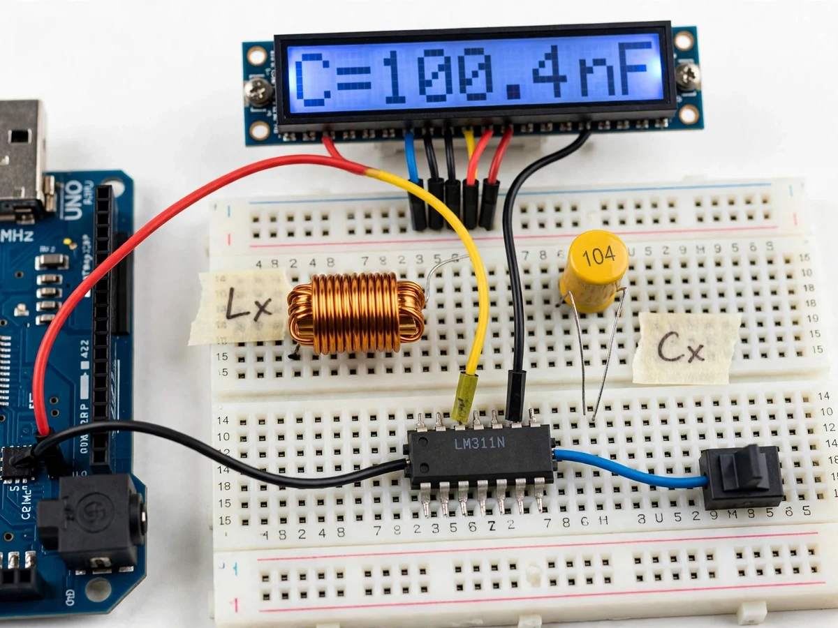
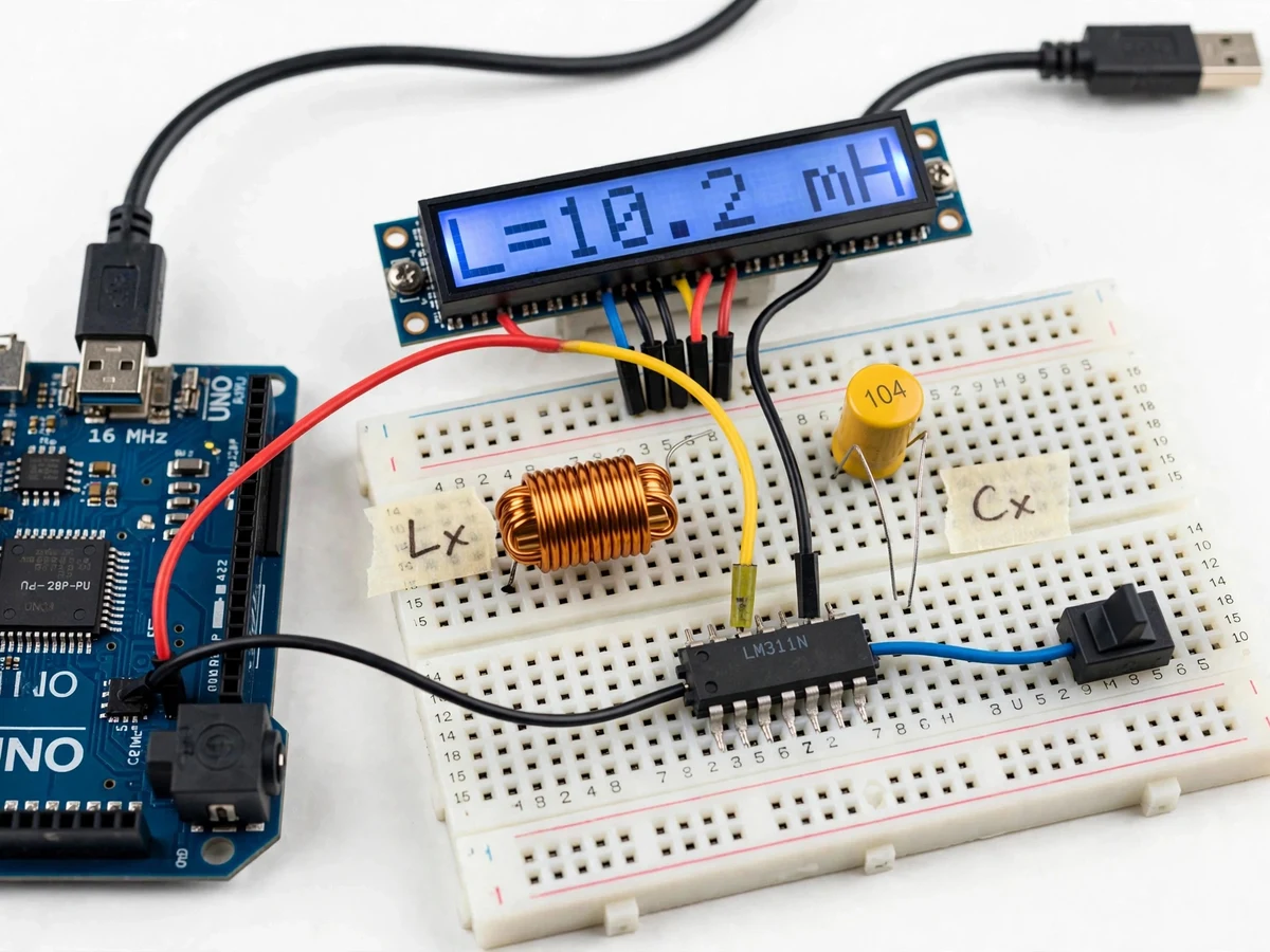
The unknown capacitor or inductor plugged into the Lx/Cx terminals, joining the reference tank.
Follow the working sequence
How it works
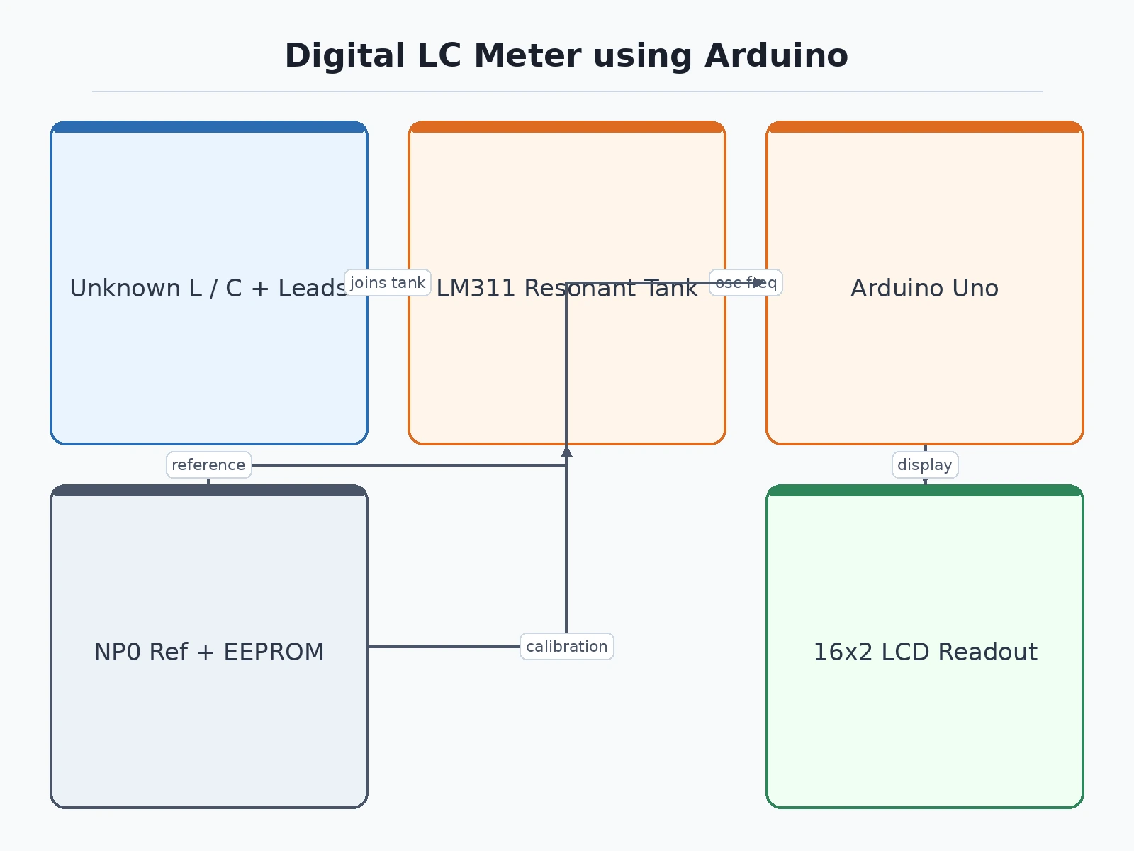
- The component under test is plugged into the Lx/Cx test terminals, joining the parallel LC tank formed with the known reference part.
- The LM311 comparator is wired as a sustaining oscillator: it feeds the tank's resonance back so the circuit oscillates continuously at the tank's natural frequency.
- The comparator's clean square-wave output drives an Arduino digital pin, where the firmware counts cycles over a fixed gate time to measure the frequency (expected up to ~500 kHz on the lowest band).
- The firmware computes the unknown from f = 1/(2π√(LC)) — solving for C when the reference is a known inductor, or for L when the reference is a known capacitor.
- The open-lead stray capacitance measured at power-up is subtracted, and the result is scaled to the best unit and shown on the LCD and the serial stream.
- For calibration, a known NP0 capacitor is measured once; the firmware back-calculates the exact reference inductance and writes it to EEPROM.
Tech stack:
- Arduino Uno (ATmega328P) · Arduino IDE (C++)
- LM311 comparator IC
- 16×2 LCD with I2C backpack
- FreqCount-style gated frequency counting
- LC parallel-resonance measurement principle
- EEPROM calibration storage
| Parameter | Value |
|---|---|
| Controller | Arduino Uno, ATmega328P at 16 MHz (datasheet) |
| Measurement principle | Parallel LC resonance sustained by an LM311 comparator; frequency counted on an Arduino digital input |
| Capacitance range | Approximately 10 pF – 100 µF across switchable bands (design target) |
| Inductance range | Approximately 1 µH – 100 mH across switchable bands (design target) |
| Display | 16 × 2 character LCD with I2C backpack, auto unit selection |
| Resolution | 4 significant digits; e.g. 0.01 pF on the lowest band (design target, band-dependent) |
| Resonant input | Expected up to ~500 kHz resonant frequency, gate-time dependent |
| Calibration | Supplied NP0 reference capacitor; constants stored in on-board EEPROM |
| Power | 5 V via USB from the Arduino (expected draw under 100 mA); optional 9 V battery pack not included |
| Output | LCD readout plus serial debug stream at 9600 baud |
Project features
- [Resonant-tank measurement core] The unknown component joins a parallel LC tank sustained by an LM311 comparator oscillator; the Arduino measures the tank's frequency on a digital input (gated counting, FreqCount-style) and computes the unknown from f = 1/(2π√(LC)).
- [Capacitance and inductance modes] A pushbutton (or automatic detection in firmware) switches between measuring an unknown capacitor against a known reference inductor and measuring an unknown inductor against a known reference capacitor.
- [16×2 LCD live readout] Every reading shows four significant digits with the auto-selected unit — pF, nF, µF, µH or mH — plus the active band, so no mental unit conversion is needed.
- [Guided reference calibration] A step-by-step routine measures the supplied NP0 reference capacitor, derives the true reference inductance and the tank's stray capacitance, and stores the constants in the Arduino's EEPROM so calibration survives power cycles.
- [Band switching] Two switchable reference bands in the base build extend the measurable range; a relay-driven fully automatic band-switching stage is available as an optional customization.
- [Open-lead zero compensation] The firmware measures stray capacitance with the test leads open and subtracts it from every reading, which is what makes the low-picofarad band usable at all.
- [Serial debug stream] Raw resonant frequency, computed value and calibration constants stream over USB at 9600 baud for the report's screenshots and for answering how-it-works questions in the viva.
What is included
- Working LC meter prototype (Arduino Uno, LM311 tank board, 16×2 LCD, test terminals)
- Complete Arduino firmware (measurement, calibration, band switching, LCD + serial output)
- Circuit diagram and wiring documentation for the tank, comparator and LCD sections
- Calibration procedure with the NP0 reference capacitor (supplied with the kit)
- Component list with part numbers and typical sources
- Project report PDF (background, resonance theory, design calculations, methodology, results)
- PPT presentation for final review
- Viva Q&A preparation document (resonance, comparator oscillator, frequency counting, error sources)
Limitations & prerequisites
- Stray capacitance and lead length dominate the lowest picofarad band — short, fixed leads and open-lead zeroing are mandatory, not optional.
- Leaky or high-ESR electrolytic capacitors read high; the meter measures value, not ESR (an ESR add-on is a listed customization).
- Ranges quoted are design targets in switchable bands; the base build ships with two bands and the wider extremes need the optional relay band-switching stage.
- Accuracy is component- and calibration-dependent — a stable NP0 reference and the calibration routine are what set the real-world figure, so no fixed accuracy percentage is claimed.
- Not a calibrated industrial instrument — it is a teaching bench tool for labs, component sorting and viva demonstrations.
Frequently Asked Questions
How does it actually measure capacitance and inductance?
The unknown part joins a parallel LC tank with a known reference component, an LM311 comparator sustains oscillation in that tank, and the Arduino counts the oscillation frequency. Since frequency depends on both parts through f = 1/(2π√(LC)), knowing one part lets the firmware solve for the other and print it on the LCD.
What ranges does it cover?
Approximately 10 pF to 100 µF for capacitance and 1 µH to 100 mH for inductance, across switchable bands — these are design targets, not measured claims. The base build ships with two reference bands; a relay-driven automatic band switch is an optional customization.
How accurate will my build be?
That depends on the reference components and the calibration routine, which is why no fixed accuracy percentage is published. A supplied NP0 reference capacitor, open-lead zeroing and short test leads are what set the real-world figure; the report documents how each error source was handled.
What does calibration involve?
You measure the supplied NP0 reference capacitor once through the guided LCD routine; the firmware back-calculates the true reference inductance and stray capacitance and stores them in EEPROM, so the calibration survives power cycles and only needs repeating if the reference parts change.
Can it measure electrolytic capacitors or ESR?
Yes, it will give a reading on electrolytic capacitors, but treat the figure with caution: leaky or high-ESR parts read high because the meter derives value from resonance, not equivalent series resistance. ESR measurement is therefore listed as an optional customization rather than part of the base build.
Is this project suitable for a final-year project?
Yes — for Electronics and Telecommunication, Electrical and Instrumentation programs. It demonstrates resonance theory, comparator-based oscillators, frequency measurement, calibration discipline and practical error analysis, all wrapped around a genuinely useful bench instrument the student keeps for years of demonstrations afterward.
Components & software requirements
- Arduino Uno (ATmega328P) · Arduino IDE (C++)
- LM311 comparator IC
- 16×2 LCD with I2C backpack
- FreqCount-style gated frequency counting
- LC parallel-resonance measurement principle
- EEPROM calibration storage
Delivery information
Built-to-order project. Delivery timeline is shared after order confirmation based on current queue.
Support terms
Complete documentation, setup guide, and viva preparation included. Support for setup and explanation provided.
Download free synopsis (PDF)
Enter your name and email — the synopsis PDF downloads immediately. We may send occasional project updates; no spam, unsubscribe anytime.