
More project photos (2)
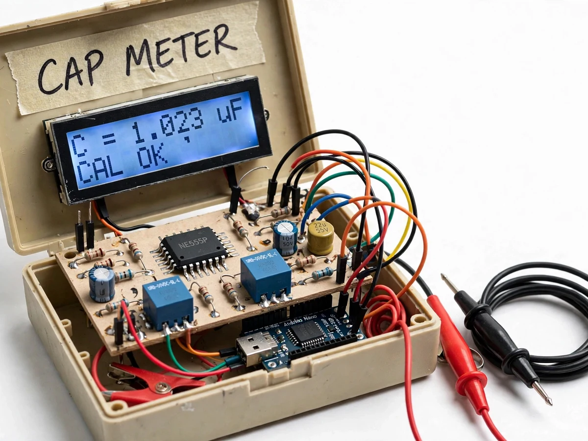
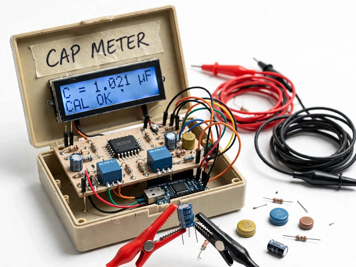
The problem
Capacitors are the components students trust the least — the markings are cryptic, salvaged parts are unmarked, and a dried-out electrolytic looks identical to a good one. A capacitance meter answers the question in seconds, and the 555-timer method is the classic student-buildable approach: wire the unknown capacitor into a 555 astable oscillator, and its value becomes a frequency through the well-known timing equation f = 1.44 / ((R1 + 2R2) × C). This project turns that equation into a complete bench instrument — 555 oscillator stage, Arduino frequency counter using input-capture timing, auto-ranging across three resistor ranges via relay switching, and a 16×2 LCD reading directly in nF/µF. The student solders a real analog front end, writes real measurement firmware (period averaging, range selection, display formatting), and calibrates the whole chain against known capacitors. It is equal parts analog electronics and embedded firmware, which is exactly what makes it a strong viva project.
How it works
- The unknown capacitor is clipped to the test terminals, becoming the timing capacitor C of the 555 astable stage with the currently selected timing resistors.
- The 555 oscillates at f = 1.44 / ((R1 + 2R2) × C); its square-wave output feeds an Arduino digital input configured for period measurement.
- The firmware captures the time between successive rising edges over multiple cycles and averages them, converting period to frequency with timer-level precision.
- Capacitance is computed by rearranging the timing equation (C = 1.44 / ((R1 + 2R2) × f)) using the known resistor values of the active range.
- If the frequency falls outside the sweet spot of the current range, the firmware switches the range relay and re-measures — auto-ranging without user input.
- The result is formatted with the appropriate unit (pF, nF or µF) and shown on the LCD along with the active range indicator.
- In calibration mode, reference capacitors are measured and a single correction factor per range is stored in EEPROM, absorbing resistor tolerances.
Tech stack:
- 555 timer astable oscillator (analog front end)
- Arduino Nano/Uno with input-capture period measurement
- Relay-switched timing resistor network (3 ranges)
- 16×2 LCD with I2C backpack
- Test clips / probe leads + discharge resistor
- EEPROM calibration storage + calibration menu
- 5 V regulated supply, stripboard/PCB front end
- Reference capacitor set for calibration
| Parameter | Value |
|---|---|
| Measurement principle | 555 astable frequency → C = 1.44/((R1+2R2)·f) |
| Ranges | 3 auto-switched, approximately 1 nF – 470 µF total (design target) |
| Display | 16×2 LCD, auto pF/nF/µF unit selection |
| Frequency method | Multi-cycle period averaging via input capture |
| Calibration | Per-range correction factor in EEPROM (reference caps) |
| Stray compensation | Open-terminal zero subtraction in firmware |
| Test connection | Front-panel clips + discharge resistor |
| Supply | 5 V regulated |
Project features
- [555 astable front end] The unknown capacitor is the timing capacitor of a 555 astable oscillator, so capacitance becomes frequency through the standard timing equation — pure analog measurement principle.
- [Precision frequency counting] The Arduino measures the oscillator period with input-capture/interrupt timing and averages multiple cycles, rather than trusting a single reading.
- [Three auto-ranges] Relay-switched timing resistors give overlapping ranges covering approximately 1 nF to 470 µF; the firmware auto-selects the range that puts the reading mid-scale.
- [Direct LCD readout] The 16×2 display shows the measured value with automatic unit selection (pF/nF/µF) and the active range — no manual math.
- [Push-to-measure test clips] The unknown capacitor connects via test clips/probe leads on the front panel, with a discharge resistor for safe handling of charged capacitors.
- [Calibration mode] A menu mode measures supplied reference capacitors and stores a correction factor in EEPROM, with the calibration procedure printed in the manual.
- [Zero/drift compensation] The firmware subtracts stray capacitance measured with open terminals, so lead capacitance does not corrupt small readings.
What is included
- Complete digital capacitance meter unit (555 front end, Arduino, relays, LCD, enclosure)
- Firmware (period measurement, auto-ranging, calibration, display)
- Front-end schematic and stripboard/PCB layout
- Calibration procedure with reference capacitor values
- Timing-equation derivation note (from the 555 datasheet theory)
- Project report PDF (background, 555 theory, design, firmware, calibration results)
- PPT presentation for final review
- Viva Q&A preparation document (astable operation, timing equation, ranging, calibration)
Limitations & prerequisites
- Measures capacitance only — it does not measure ESR or leakage, so a capacitor can read the right value and still be faulty in-circuit; the report states this boundary.
- Range and accuracy figures are design targets; the actual calibrated accuracy is established on the buyer's build with the supplied reference capacitors and calibration procedure — no accuracy is claimed before that.
- Very small capacitances (tens of pF) are dominated by stray/lead capacitance even with zero compensation; the lowest range is indicative rather than precision.
- Large electrolytics need a discharge wait before measurement; the manual's discharge procedure must be followed for safety and accuracy.
- The 555's temperature drift affects the timing equation slightly; measurements assume room-temperature bench conditions.
Frequently Asked Questions
How does a 555 timer measure capacitance?
In astable mode the 555 charges and discharges the timing capacitor through the timing resistors, producing a square wave whose frequency is f = 1.44 / ((R1 + 2R2) × C). Measure the frequency precisely and the capacitance follows by algebra — the meter is really a precision frequency counter wrapped around this equation.
Why three ranges instead of one?
One resistor set cannot cover 1 nF to 470 µF — the frequency would swing from megahertz to millihertz. Three switched resistor values keep the 555 in its clean, stable operating band on every range, and the firmware picks the right one automatically.
What does calibration actually correct?
Resistor tolerances and 555 threshold variations shift every reading by a near-constant factor per range. Measuring known reference capacitors lets the firmware store one correction factor per range in EEPROM, absorbing all of it at once.
Why measure the period instead of counting pulses?
At the low frequencies of the large-capacitance range, counting pulses for a fixed gate time is slow and coarse. Measuring the time for N cycles with the hardware timer gives high resolution at any frequency, which is why input capture is used.
Can it test capacitors still soldered in a circuit?
Not reliably — parallel components in-circuit corrupt the reading. The manual requires the capacitor to be removed (or at least one leg lifted) before measurement.
Is this project suitable for a final-year project?
Yes — for Electronics and Telecommunication programs. It combines a real analog front end (555 astable design) with embedded measurement firmware and a proper calibration story for the viva. Suitable for B.E./B.Tech final-year projects in Electronics and Telecommunication Engineering.
Components & software requirements
- 555 timer astable oscillator (analog front end)
- Arduino Nano/Uno with input-capture period measurement
- Relay-switched timing resistor network (3 ranges)
- 16×2 LCD with I2C backpack
- Test clips / probe leads + discharge resistor
- EEPROM calibration storage + calibration menu
- 5 V regulated supply, stripboard/PCB front end
- Reference capacitor set for calibration
Delivery information
Built-to-order project. Delivery timeline is shared after order confirmation based on current queue.
Support terms
Complete documentation, setup guide, and viva preparation included. Support for setup and explanation provided.