
More project photos (2)
The problem
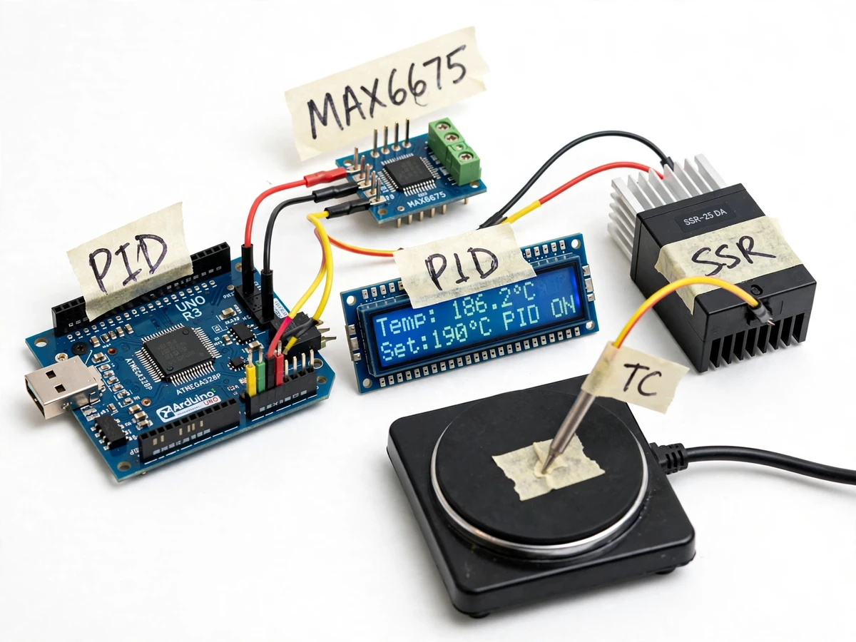
Hand-soldering SMD parts with an iron works for one-off joints, but reflow soldering — where paste melts through a controlled temperature profile — needs the board heated through specific phases, not just left on a hot burner. Overshoot the soak and the flux chars; overshoot the peak and parts tombstone or the board scorches; undershoot and the joints never wet. A dumb hotplate offers no control at all, and commercial reflow stations hide their control behind a sealed, fixed menu. This project builds the controller that closes that gap: an Arduino Uno running a PID loop, a K-type thermocouple digitized by a MAX6675 module feeding back the plate temperature, and an optoisolated solid-state relay switching the mains hotplate with time-proportioned drive. The firmware walks the plate through a soak-and-reflow profile — preheat, soak hold, ramp to reflow peak, then cooldown — with temperature, setpoint and profile phase on a 16x2 LCD. Every setpoint, phase time and PID gain is a configurable constant, so the student demonstrates closed-loop thermal control, not just relay switching.
K-type thermocouple digitized by the MAX6675 at 0.25 C resolution with cold-junction compensation, sampled about once per second.
Follow the working sequence
How it works
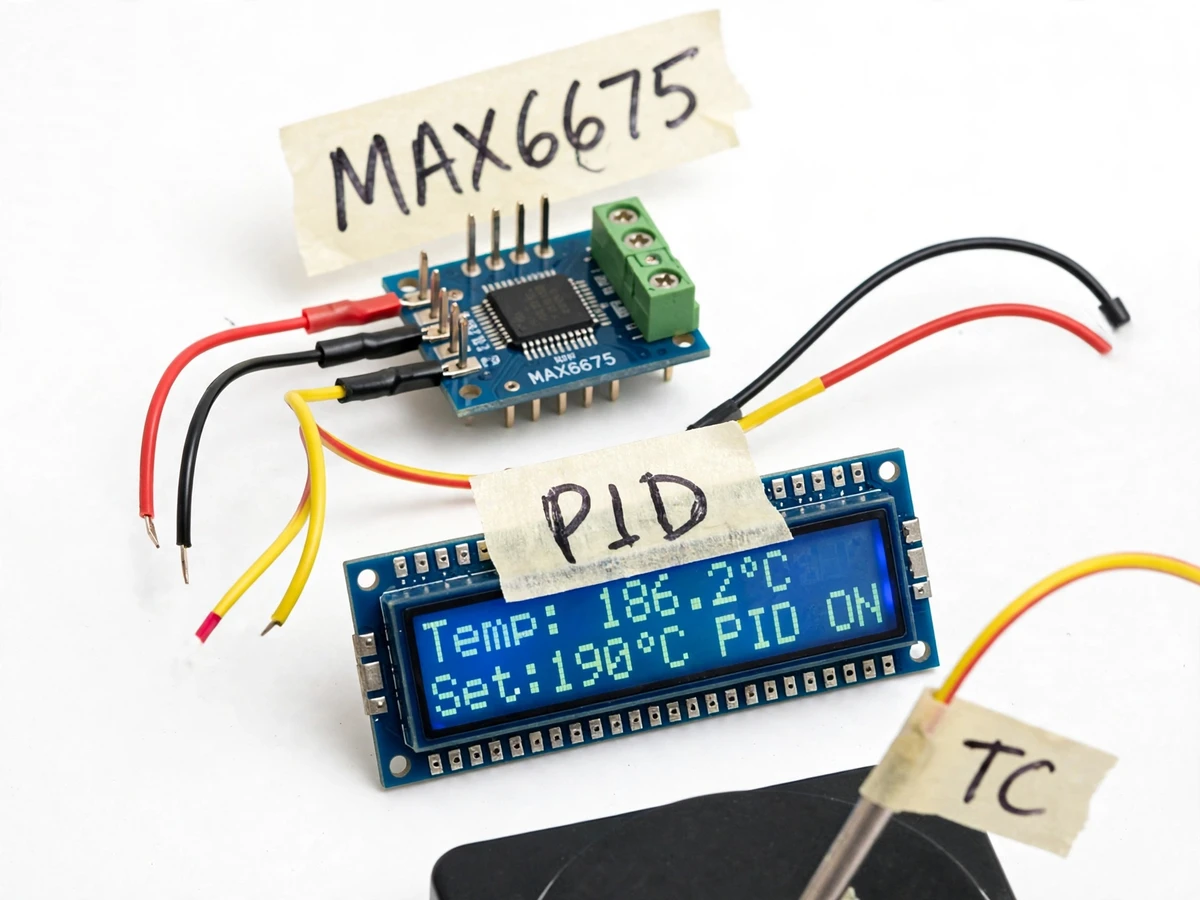
- The K-type thermocouple tip is clamped to the hotplate surface and wired to the MAX6675 module's screw terminals; the module digitizes the temperature at 0.25 °C resolution over SPI with cold-junction compensation handled on-chip, and the Arduino samples it about once per second.
- The firmware compares the reading against the active setpoint — either the manual target or the current phase of the reflow profile — and computes the temperature error.
- The PID loop turns the error into a 0–100% drive command from the configured Kp, Ki and Kd gains, with anti-windup limiting the integral term so the heater does not stay saturated after a long ramp.
- The drive command becomes time-proportioned switching: inside each control window (design target 2 s), the SSR is on for the commanded fraction of the window, giving smooth analog-like power control from one digital output.
- The optoisolated, zero-crossing SSR switches the 230 VAC hotplate while the 5 V logic stays galvanically isolated from mains; all high-voltage wiring sits in a fused, enclosed section of the build.
- The profile sequencer advances the phases automatically — soak at approximately 150 °C for 60–90 s, ramp to the reflow peak of approximately 220–240 °C held 30–60 s, then the SSR releases and the plate cools — with the current phase on the LCD; an open-thermocouple reading forces the SSR off at any point.
Tech stack:
- Arduino Uno (ATmega328P) · 5 V logic
- MAX6675 module · K-type thermocouple
- Solid-state relay (optoisolated, 240 VAC)
- 16x2 character LCD (HD44780 with I2C backpack)
- Arduino IDE (C/C++ firmware)
- Single-burner electric hotplate (230 VAC mains)
- Rotary encoder · push buttons
- Terminal blocks · fused mains enclosure
| Parameter | Value |
|---|---|
| Controller | Arduino Uno, ATmega328P, 16 MHz (datasheet value) |
| Temperature sensor | K-type thermocouple probe (probe class, component-dependent) |
| Thermocouple interface | MAX6675 module, 12-bit, 0.25 °C resolution, SPI read-only (datasheet) |
| Cold-junction compensation | On-chip, automatic (datasheet feature) |
| Converter accuracy | 8 LSBs (approximately ±2 °C) from 0 °C to +700 °C (datasheet) |
| Read range | 0 °C to +1024 °C converter capability (datasheet); reflow profile uses approximately 25–240 °C (design target) |
| Control method | Discrete PID, configurable Kp/Ki/Kd with anti-windup (firmware) |
| Output drive | Time-proportioned SSR drive, control window approximately 2 s (design target) |
| Soak phase | Approximately 150 °C, hold 60–90 s (design target, configurable) |
| Reflow peak phase | Approximately 220–240 °C, hold 30–60 s (design target, configurable) |
| SSR rating | 25 A at 240 VAC, zero-crossing, optoisolated (component rating; prototype duty lower) |
| Hotplate class | Single-burner electric hotplate, approximately 1000 W at 230 VAC (design target, component-dependent) |
| Display | 16x2 character LCD, temperature/setpoint/phase/drive readout |
| Failsafe | Open-thermocouple detection forces SSR drive off (firmware) |
| Logic supply | 5 V DC via USB or barrel jack |
| Prototype scale | Bench-scale controller plus hotplate; mains section in fused, enclosed box |
Project features
- [PID closed-loop control] The firmware runs a discrete PID loop on the measured plate temperature with configurable Kp, Ki and Kd gains and anti-windup on the integral term, so the plate settles toward its setpoint with less overshoot and hunting than simple on/off control.
- [MAX6675 thermocouple interface] A K-type thermocouple is digitized by the MAX6675 module — 12-bit resolution at 0.25 °C per LSB over an SPI read-only interface with on-chip cold-junction compensation and open-thermocouple detection (datasheet values).
- [Reflow profile sequencer] The firmware walks the plate through preheat, soak, ramp-to-peak and cooldown phases with configurable time-temperature setpoints, so a full soak-and-reflow cycle runs automatically from one start command.
- [Optoisolated SSR mains switching] A zero-crossing solid-state relay switches the 230 VAC hotplate while the Arduino side stays galvanically isolated from mains — the low-voltage logic never touches the high-voltage section.
- [LCD readout and setpoint entry] A 16x2 LCD shows the live plate temperature, active setpoint, profile phase and PID drive level, while a rotary encoder and push buttons set the target temperature and profile times.
- [Thermocouple failsafe] The firmware watches the MAX6675 open-thermocouple detection bit; a disconnected or broken probe forces the SSR drive off immediately instead of running the heater blind.
- [Tunable at the bench] Every gain and phase time is a constant the student can change and re-demonstrate, and the tuning procedure shows how to raise Kp for response or Ki for steady-state error on the actual build.
What is included
- Working PID controller prototype (Arduino board, MAX6675 module, SSR, 16x2 LCD, rotary encoder and push buttons, wired on a base with an enclosed mains section)
- Arduino firmware source with PID loop, reflow profile sequencer, LCD user interface and configurable gains and phase times
- Circuit and wiring documentation (schematic-style diagrams, pin map, mains-enclosure wiring and fusing notes)
- Component list with ratings (SSR, thermocouple type, fuse, terminal blocks)
- Reflow profile table and a PID gain-tuning procedure for the student's own build
- Project report PDF (background, PID control theory, profile design, methodology, test log)
- PPT presentation for final review
- Viva Q&A preparation document (PID tuning, thermocouple interfacing, SSR isolation, mains safety)
Limitations & prerequisites
- The hotplate runs on 230 VAC mains: the enclosure must be closed and fused, and the mains wiring checked by someone qualified before the first powered run. The prototype is a bench demonstration, not a certified appliance.
- Never probe, touch or open the mains section while it is powered; keep it closed during every run and never leave a heated hotplate unattended.
- The thermocouple tip must be firmly clamped to the plate surface: a loose tip reads low and the PID will overdrive the heater, so placement is verified before every profile run.
- The SSR needs a heatsink or derated duty at high load; its temperature rise must be checked before long runs.
- The MAX6675 converts at approximately ±2 °C accuracy class (8 LSBs, 0–700 °C, datasheet) — it is a profile controller, not a calibration reference.
- PID gains and profile times are design targets; actual thermal response depends on the hotplate used and must be tuned with the included procedure.
- The controller holds the plate temperature profile — reflow quality also depends on solder paste, board mass and airflow, which are outside the controller's scope.
Frequently Asked Questions
Is this project suitable for a final-year project?
Yes — for Electronics and E&TC programs. It demonstrates PID closed-loop control, SPI sensor interfacing, thermocouple measurement with on-chip cold-junction compensation, mains switching through an optoisolated SSR, and mains-safety design — every part examinable on hardware the student built and tuned.
Which controller and sensor interface are used?
An Arduino Uno (ATmega328P) with a MAX6675 module on an SPI read-only interface: 12-bit conversion, 0.25 °C resolution, automatic cold-junction compensation and open-thermocouple detection (datasheet values). The K-type thermocouple connects to the module's screw terminals.
What does the reflow profile look like?
The design-target profile is preheat, then a soak at approximately 150 °C for 60–90 s, a ramp to the reflow peak of approximately 220–240 °C held for 30–60 s, then cooldown with the SSR released. Every setpoint and phase time is configurable in firmware.
How is the mains hotplate switched safely?
Through an optoisolated, zero-crossing SSR, so the 5 V Arduino side is galvanically isolated from the 230 VAC section, which is fused and enclosed. The logic board is never wired into the mains side; the build must be checked by someone qualified before first use.
Can the PID gains be tuned?
Yes. Kp, Ki and Kd are firmware constants that can be changed at the bench, and the included tuning procedure shows how to adjust them on the student's own hotplate. Published gains are design targets, not measured optima for every build.
What power supplies does it need?
The Arduino and logic run on 5 V via USB or the barrel jack; the hotplate itself runs on 230 VAC mains through the SSR; the thermocouple is a passive sensor and needs no power.
Components & software requirements
- Arduino Uno (ATmega328P) · 5 V logic
- MAX6675 module · K-type thermocouple
- Solid-state relay (optoisolated, 240 VAC)
- 16x2 character LCD (HD44780 with I2C backpack)
- Arduino IDE (C/C++ firmware)
- Single-burner electric hotplate (230 VAC mains)
- Rotary encoder · push buttons
- Terminal blocks · fused mains enclosure
Delivery information
Built-to-order project. Delivery timeline is shared after order confirmation based on current queue.
Support terms
Complete documentation, setup guide, and viva preparation included. Support for setup and explanation provided.
Download free synopsis (PDF)
Enter your name and email — the synopsis PDF downloads immediately. We may send occasional project updates; no spam, unsubscribe anytime.