
More project photos (2)
The problem
Line following is one of the oldest navigation tricks in mobile robotics — the principle behind warehouse AGVs following floor strips between shelves. Industrial AGVs read magnetic tape, laser reflectors or painted lanes; a student robot reads a black tape line with a row of infrared sensors and steers a two-wheel differential-drive chassis along it. Most student builds steer with bang-bang logic: if the line is left, swing left hard. That works on gentle tracks but wobbles through curves and loses the line at sharp bends. This project replaces that logic with a PID controller, the workhorse loop of industrial automation: proportional gain reacts to the current offset, integral gain corrects accumulated drift, and derivative gain damps the oscillation that causes wobble. Five TCRT5000 sensors feed a weighted line position to the firmware, which turns that error into smooth differential PWM for two DC gear motors through an L298N driver. An HC-SR04 ultrasonic sensor on a scanning servo overrides line-following when an obstacle blocks the path — stop, scan both sides, steer toward the clearer side, then re-acquire the line.
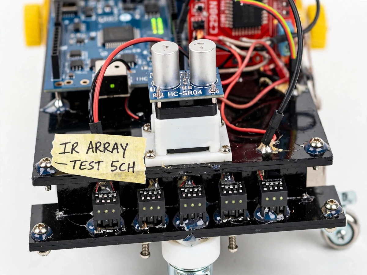
Five TCRT5000 channels a few millimetres above the floor report where the black tape sits under the array; the firmware computes a weighted line-position error.
Follow the working sequence
How it works
- The five TCRT5000 sensors sit a few millimetres above the floor under the robot's front edge. Each emits 950 nm infrared and reads the reflection: white floor reflects it back, black tape absorbs it, so the channels report exactly where the line sits under the array.
- The Arduino samples all five channels and computes a weighted position value — the line's offset from center — which becomes the error term for the control loop.
- The PID loop converts that error into a correction: Kp scales the current error, Ki accumulates past error to fix slow drift, and Kd reacts to how fast the error is changing, damping the wobble that plain threshold steering causes.
- The correction is applied differentially — added to one motor's PWM and subtracted from the other's through the L298N — so the robot arcs smoothly through curves instead of zig-zagging.
- Every control cycle the HC-SR04 pings the path ahead; if the echo reports an obstacle inside the configured stop distance, line-following pauses, the robot halts, the servo sweeps the sensor left and right, and the robot turns toward the clearer side.
- After clearing the obstacle, the robot runs a re-acquire sweep — a slow forward arc until the IR array sees the line again — then resumes PID tracking with the same tuned constants.
Tech stack:
- Arduino Uno (ATmega328P) · Arduino IDE
- Embedded C firmware
- 5-channel IR array · TCRT5000
- L298N motor driver · dual H-bridge
- HC-SR04 ultrasonic · SG90 servo
- DC gear motors · differential drive
- PID control loop · PWM
- 4xAA pack / 2S Li-ion power
| Parameter | Value |
|---|---|
| Controller | Arduino Uno, ATmega328P at 16 MHz, 14 digital I/O, 6 analog inputs (datasheet) |
| Line sensors | 5-channel TCRT5000 array, 950 nm emitter, 0.2–15 mm operating range (datasheet) |
| Motor driver | L298N dual H-bridge, 2 A per channel, ~2 V saturation drop (datasheet) |
| Obstacle sensor | HC-SR04 ultrasonic, 2–400 cm range, ±3 mm accuracy (datasheet) |
| Drive motors | 2 × DC gear motors, approximately 150 RPM at 6 V (motor-dependent) |
| Control loop | PID update approximately 50–100 Hz (design target) |
| PID constants | Tuned per track with the buyer-run procedure (no universal values claimed) |
| Line specification | Black tape line, approximately 19–25 mm wide on a matte floor (design target) |
| Obstacle stop distance | Configurable, default approximately 15–20 cm |
| Chassis | 2-wheel differential chassis with front caster, approximately 200 × 150 mm (design target) |
| Power supply | 4 × AA cells (6 V) or 2S Li-ion (~7.4 V nominal), motors and logic on separate feeds |
Project features
- [PID line tracking] Five TCRT5000 IR channels feed a weighted line-position estimate into a PID loop — Kp reacts to the current offset, Ki corrects accumulated drift and Kd damps oscillation — producing smooth steering through curves. Constants ship with documented defaults and are tuned to the buyer's track with the included procedure.
- [Differential drive with PWM speed control] Two DC gear motors on an L298N dual H-bridge receive independent PWM, so the robot arcs through bends by slowing one wheel instead of stopping to pivot — the same differential principle used in warehouse robots.
- [Obstacle override with HC-SR04] The ultrasonic sensor continuously measures the path ahead (2–400 cm datasheet range); when an obstacle is detected inside the configured stop distance, line-following pauses and the robot halts before contact.
- [Scanning servo mount] The HC-SR04 sits on an SG90 servo that sweeps left and right once the robot stops; the firmware compares both side clearances and steers toward the wider gap before re-acquiring the line.
- [Per-channel IR calibration] Each sensor channel has a trimpot threshold adjustment with a documented calibration routine for different floor materials and ambient light, plus on-board LEDs showing each channel's live state for debugging.
- [Buyer-run PID tuning procedure] A step-by-step procedure for finding Kp, Ki and Kd on the actual track — start with Kp alone, add Kd to kill wobble, then Ki for steady-state drift — so the tuning numbers in the report are the student's own work, honestly documented.
- [Separated power layout] The motors run from the battery through the L298N while the Arduino takes its own regulated feed, with wiring notes explaining the driver's ~2 V drop and stall current, so the electronics survive real demo conditions.
- [Debug telemetry] Per-channel IR status LEDs plus serial output of the line error and correction values let the student watch the PID respond in real time during tuning sessions.
What is included
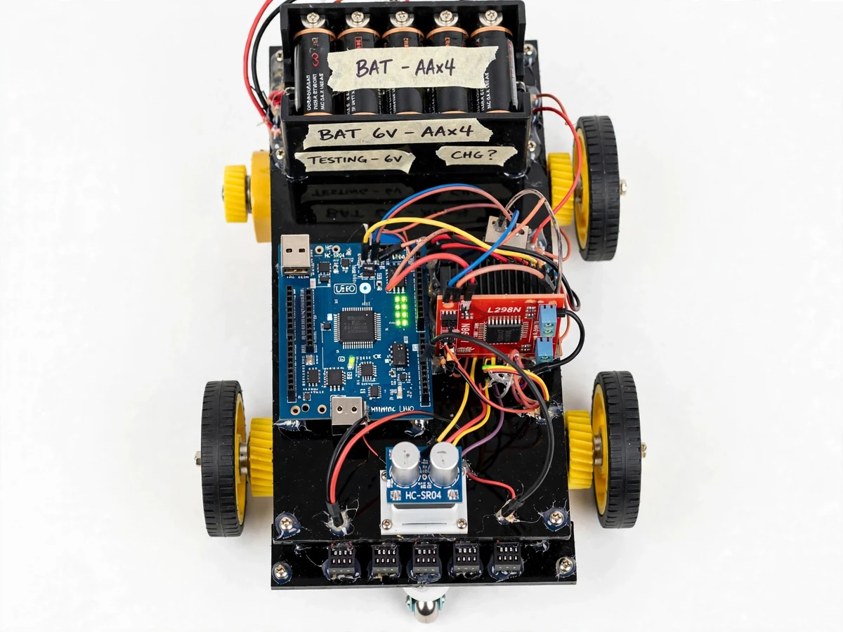
- Assembled line-follower robot (chassis, IR array, Arduino Uno, L298N driver, servo-mounted HC-SR04, battery box)
- Arduino firmware source with comments (PID loop, obstacle override, calibration routines)
- Wiring diagram and power-supply notes (L298N ~2 V drop, separate motor/logic feeds)
- Buyer-run IR calibration and PID tuning procedures
- Component list with part numbers
- Project report PDF (background, control theory, methodology, the student's own tuning results)
- PPT presentation for final review
- Viva Q&A preparation document (PID tuning, differential drive, sensor principles)
- Demonstration guidance (track setup, tape line, obstacle placement)
Limitations & prerequisites
- PID constants are track-specific — there are no universal values; tuning takes a real track session, and no lap time or completion claim is made without the buyer's own measurements.
- IR reflectance depends on floor material and lighting; glossy floors and strong direct sunlight can confuse the array despite its daylight filters, so calibration is required per surface.
- The L298N drops roughly 2 V across its output stage, so the motors see less than the battery voltage and the driver heats up under stall — demo runs are kept short and wheels are never held stalled.
- The HC-SR04 has a ~2 cm blind zone and can miss soft, steeply angled or very thin obstacles; avoidance is stop-scan-turn, not path planning, and it cannot see drop-offs or track gaps.
- Fresh AA cells give roughly 30–45 minutes of running (expected, load-dependent); longer sessions need the optional 2S Li-ion pack.
- This is an educational robotics prototype demonstrating AGV navigation principles — it is not an industrial vehicle and carries no safety certification.
Frequently Asked Questions
Which controller is used, and why an Arduino?
An Arduino Uno (ATmega328P, 16 MHz). The entire control loop — five analog reads, PID math, PWM output and ultrasonic timing — fits easily in its resources, and the serial monitor is genuinely useful for watching the line error change live while tuning. The hardware is cheap, replaceable and familiar to any viva examiner.
How does the PID steering actually work?
Each cycle the firmware turns the five IR readings into a line-offset error. The proportional term steers back in proportion to that error, the integral term fixes slow drift off-center, and the derivative term damps the wobble that makes threshold-based robots zig-zag. Kp, Ki and Kd are tuned to the track with the included procedure.
What happens when the robot meets an obstacle?
The HC-SR04 watches the path ahead. Inside the configured stop distance, line-following pauses and the robot halts. The SG90 servo sweeps the sensor left and right, the firmware compares the clearances, turns toward the wider gap, runs a re-acquire sweep until the IR array finds the line, and resumes PID tracking.
What track and power supply does it need?
A flat matte floor with a black tape line roughly 19–25 mm wide — standard electrical tape works. Power is 4 × AA cells (6 V) or a 2S Li-ion pack (~7.4 V); motors and the Arduino run on separate feeds per the wiring notes, and fresh AAs last about 30–45 minutes of running.
Can it be customized, for example with Bluetooth control?
Yes. The most requested addition is an HC-05 Bluetooth module for a manual-override remote-control mode; other options include a junction-counting mode for maze solving or a 2S Li-ion pack for longer runtimes. Customizations are developed on request and quoted separately — they are not part of the base build.
Is this project suitable for a final-year project?
Yes — for Electronics & Telecommunication, Electrical and Mechatronics programs. It demonstrates control-system theory (PID tuning), sensor interfacing and calibration, differential-drive kinematics and embedded C — a complete sense–decide–actuate loop with honest, student-measured tuning data and a working obstacle-avoidance demo for the viva. problem: Students learn PID control, motor drives and sensor interfacing as isolated theory, while the mobile robots that actually use them — warehouse AGVs following floor strips — feel like industrial black boxes. Cheap line-follower kits teach wiring but steer with bang-bang threshold logic, so students never see why control theory exists. This project closes that gap: a robot that follows a black tape line with a real PID loop, and handles obstacles with an ultrasonic override, giving the student a working control-systems demonstrator they tuned themselves. concept: A 5-channel TCRT5000 IR array under the robot's front edge detects a black tape line and reports a weighted position to an Arduino Uno. A PID loop converts that position error into differential PWM for two DC gear motors via an L298N driver — Kp handles the current offset, Ki the accumulated drift, Kd the wobble — so the robot arcs smoothly through curves. An HC-SR04 ultrasonic sensor on an SG90 servo continuously checks the path ahead; on detecting an obstacle inside the stop distance, line-following pauses, the robot halts, the servo scans both sides, and the robot turns toward the clearer gap before re-acquiring the line. Kp, Ki and Kd are tuned to the track with a documented buyer-run procedure, and per-channel IR trimpots calibrate the array to the floor. features:
- 5-channel TCRT5000 IR array feeding a weighted line-position estimate into a PID loop
- Kp/Ki/Kd tuning with documented defaults and a buyer-run track-tuning procedure
- Differential-drive steering: independent PWM to each motor via L298N, arcs through curves
- HC-SR04 obstacle override: stop, scan both sides with an SG90 servo, steer to the clearer gap
- Line re-acquire sweep after obstacle clearance
- Per-channel IR threshold trimpots with a calibration routine for different floors
- Separated motor/logic power feeds with wiring notes on the L298N ~2 V drop
- Debug telemetry: per-channel LEDs plus serial output of error and correction values requirements:
- Arduino Uno board and USB cable
- 5-channel TCRT5000 IR sensor array module
- L298N motor driver module
- HC-SR04 ultrasonic sensor and SG90 micro servo
- 2 × DC gear motors with wheels, robot chassis, front caster
- 4 × AA battery holder (or 2S Li-ion pack) and jumper wires
- Flat matte floor and black electrical tape (~19–25 mm line) for the test track
- Computer with Arduino IDE for firmware upload and PID tuning deliverables:
- Assembled line-follower robot (chassis, sensors, Arduino, driver, servo, battery box)
- Arduino firmware source with comments (PID loop, obstacle override, calibration routines)
- Wiring diagram and power-supply notes
- Buyer-run IR calibration and PID tuning procedures
- Component list with part numbers
- Project report PDF (background, control theory, methodology, tuning results)
- PPT presentation for final review
- Viva Q&A preparation document
- Demonstration guidance (track setup, obstacle placement) limitations:
- PID constants are track-specific; tuning needs a real track session and no lap-time claim is made without the buyer's measurements
- IR sensing depends on floor material and lighting; calibration required per surface
- L298N drops ~2 V and heats under stall; short demo runs, never hold wheels stalled
- HC-SR04 has a ~2 cm blind zone and can miss soft or angled obstacles; stop-scan-turn only, not path planning
- ~30–45 min runtime on fresh AA cells (expected); longer sessions need the optional 2S pack
- Educational prototype demonstrating AGV principles, not an industrial vehicle timeline:
- Typical built-to-order delivery: chassis and electronics assembly with wiring in the first week, firmware (PID loop, obstacle override, calibration routines) in the second, tuning procedures plus report/PPT/viva documentation in the third, with the finished robot test-run on a tape track before handover. Exact schedule is confirmed at order time. support:
- Explanation support covers the full control chain: how each IR channel reads the line, how the weighted position becomes the PID error, what Kp/Ki/Kd each do and how the tuning procedure finds them, how differential PWM steers the chassis, and how the ultrasonic override and re-acquire sweep work — so the student can answer viva questions on every part. Report, PPT and viva Q&A are included; code walkthrough provided on request.
Components & software requirements
- Arduino Uno (ATmega328P) · Arduino IDE
- Embedded C firmware
- 5-channel IR array · TCRT5000
- L298N motor driver · dual H-bridge
- HC-SR04 ultrasonic · SG90 servo
- DC gear motors · differential drive
- PID control loop · PWM
- 4xAA pack / 2S Li-ion power
Delivery information
Built-to-order project. Delivery timeline is shared after order confirmation based on current queue.
Support terms
Complete documentation, setup guide, and viva preparation included. Support for setup and explanation provided.
Download free synopsis (PDF)
Enter your name and email — the synopsis PDF downloads immediately. We may send occasional project updates; no spam, unsubscribe anytime.