
More project photos (2)
The problem
Electronics students and hobbyists accumulate drawers of loose 74xx and 40xx logic ICs — bought loose from local shops, pulled from old boards, or swapped between lab benches. A dead or mislabelled IC then wastes hours of debugging: the circuit is blamed, wiring is re-checked, and the actual faulty chip is only suspected last. A multimeter cannot verify logic function, and professional IC testers cost far more than a student budget allows. This project closes that gap with a purpose-built digital IC tester: the unknown IC goes into a ZIF test socket, an Arduino applies every truth-table input combination to its pins, and the 16x2 LCD reports either PASS/FAIL with the failing gate identified, or — when the part number itself is unknown — the auto-identified part number from the onboard library. It turns a drawer of mystery chips into verified, usable components.
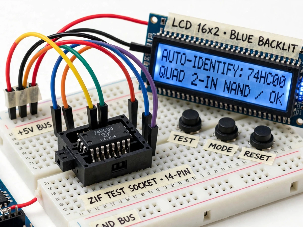
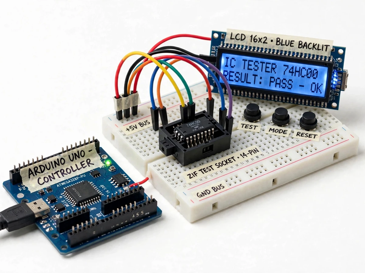
Seats the IC in the ZIF socket and runs TEST, MODE and RESET from the push buttons.
Follow the working sequence
How it works
- The IC under test is placed in the ZIF test socket; the Arduino powers the socket at 5 V and maps VCC/GND pins from the firmware pin-layout table (e.g. pin 14/7 for 14-pin DIP).
- Pressing TEST starts the cycle: the firmware drives the input pins through every truth-table combination for the selected IC.
- After each vector, the Arduino reads the output pins and compares them against the expected values stored in the onboard library.
- In AUTO mode with an unknown IC, the response signature from the probing sequence is compared against every library entry and the closest match is identified.
- The 16x2 LCD shows the identified part number (or the selected test IC), then the result: PASS, or FAIL with the failing gate and pin number.
- MODE cycles through the IC library for selecting a specific part to test; RESET clears the result and re-arms the tester.
- An optional serial log dumps the full per-vector results to the PC for inclusion in the report.
Tech stack:
- Arduino Uno (ATmega328P)
- ZIF test socket (14-pin, 16-pin DIP compatible)
- 16x2 LCD display (blue backlit, I2C adapter)
- Tactile push buttons with pull-up resistors
- Truth-table signature library (firmware)
- Jumper wires and solderless breadboard
- Arduino IDE (embedded C firmware)
- USB 5 V power supply
| Parameter | Value |
|---|---|
| Controller | ATmega328P on Arduino Uno, 16 MHz (datasheet value) |
| Supported IC families | 74xx, 74HC, 74HCT, 40xx series at 5 V logic |
| Supported packages | 14-pin and 16-pin DIP (firmware-configurable pin maps) |
| Test method | Truth-table vector application with pin-level output comparison |
| Onboard library | Approximately 25 common 14/16-pin part numbers (design target, expandable in firmware) |
| Test cycle time | Under approximately 2 seconds per 14-pin gate IC (design target, expected) |
| Display | 16x2 character LCD, blue backlit |
| User interface | TEST, MODE, RESET tactile buttons |
| Power | 5 V DC via USB (expected) |
| Output | LCD result + optional serial per-vector log |
Project features
- [Auto-identification of unknown ICs] Insert an unlabelled 14-pin or 16-pin IC into the ZIF socket and press TEST — the firmware applies probing vectors, builds a response signature, and matches it against the onboard library, displaying the identified part number (e.g. 74HC00, 74HC74) on the LCD.
- [Truth-table functional testing] For a known IC, every row of its truth table is applied to the input pins and each output is compared against the expected logic; the LCD reports PASS or names the failing gate and pin.
- [Onboard 74xx/40xx library] Firmware carries a truth-table database of the most-used 14-pin and 16-pin DIP logic ICs — NAND, NOR, AND, OR, XOR, NOT gates, flip-flops, buffers and decoders — with MODE browsing on the LCD.
- [ZIF test socket] A zero-insertion-force socket means the IC drops in and out without levering pins, so repeated testing never bends or breaks leads.
- [16x2 LCD result display] Blue-backlit character display shows the identified part, test progress, and PASS/FAIL with failing-gate detail — no serial monitor needed during a demo.
- [TEST/MODE/RESET interface] Three tactile push buttons run a one-touch test cycle, browse the IC library, and reset the tester state.
- [Buyer-run verification routine] Firmware includes a self-check routine that runs against a known-good reference IC, so the student confirms the tester reads correctly on their own build after assembly.
What is included
- Working digital IC tester prototype (Arduino, ZIF socket assembly, LCD, buttons, wiring)
- Arduino firmware source code with the 74xx/40xx truth-table library
- Wiring diagram and circuit documentation
- Component list with exact part numbers
- Buyer-run verification procedure using a known-good reference IC
- Project report PDF (background, methodology, working, results, limitations)
- PPT presentation for final review
- Viva Q&A preparation document (logic families, truth tables, ZIF, firmware flow)
Limitations & prerequisites
- Tests 14-pin and 16-pin DIP packages only in the base build; 20/24-pin packages need different hardware and are out of scope.
- 40xx CMOS ICs are tested at 5 V here — operation at 12 V or 15 V rails, common in some 40xx circuits, is not verified.
- This is a functional logic test only: it does not measure propagation delay, rise/fall time or fan-out, so a timing-marginal IC can pass and still fail in a fast circuit.
- Auto-identification only recognizes ICs present in the onboard library (approximately 25 part numbers); anything else reports NOT IN LIBRARY.
- The tester has no protection against ICs with dead internal shorts — a shorted device can stress Arduino I/O pins, so the buyer-run procedure starts with a multimeter continuity check.
- Test vectors assume standard 5 V logic thresholds; 3.3 V-only logic families are out of scope.
- This is an academic test instrument, not a substitute for the manufacturer's datasheet or certified automated test equipment.
Frequently Asked Questions
Which IC families can it test?
The 74xx, 74HC, 74HCT and 40xx series in 14-pin and 16-pin DIP packages at 5 V logic. The onboard library covers the most-used gates, flip-flops, buffers and decoders — about 25 part numbers as a design target — and new parts can be added in firmware.
How does auto-identification work?
The firmware applies a probing sequence to the inserted IC, records the input-output response as a signature, and compares it against every stored library entry. The matching part number is shown on the LCD; if nothing matches, it reports NOT IN LIBRARY.
Which controller is used and why?
An Arduino Uno (ATmega328P). A logic tester needs only digital I/O pins and simple comparison logic, so a full development board keeps the design student-buildable and easy to explain in a viva.
What power supply does it need?
Standard 5 V from the Arduino's USB connection. The ICs under test are powered from the same 5 V rail, which suits 74xx/74HC/74HCT and 40xx parts operated at 5 V.
Can I add my own ICs to the library?
Yes — each library entry is a truth table plus a pin map in the firmware, and the documentation explains the exact format, so adding a part is a defined procedure rather than a rewrite.
Is this project suitable for a final-year project?
Yes — for Electronics & Telecommunication and Electrical programs. It demonstrates digital logic fundamentals, truth tables, embedded firmware design, and test automation, all with a genuinely useful instrument as the outcome. Suitable for B.E./B.Tech final-year projects in Electronics & Telecommunication and Electrical engineering.
Components & software requirements
- Arduino Uno (ATmega328P)
- ZIF test socket (14-pin, 16-pin DIP compatible)
- 16x2 LCD display (blue backlit, I2C adapter)
- Tactile push buttons with pull-up resistors
- Truth-table signature library (firmware)
- Jumper wires and solderless breadboard
- Arduino IDE (embedded C firmware)
- USB 5 V power supply
Delivery information
Built-to-order project. Delivery timeline is shared after order confirmation based on current queue.
Support terms
Complete documentation, setup guide, and viva preparation included. Support for setup and explanation provided.
Download free synopsis (PDF)
Enter your name and email — the synopsis PDF downloads immediately. We may send occasional project updates; no spam, unsubscribe anytime.