
More project photos (2)
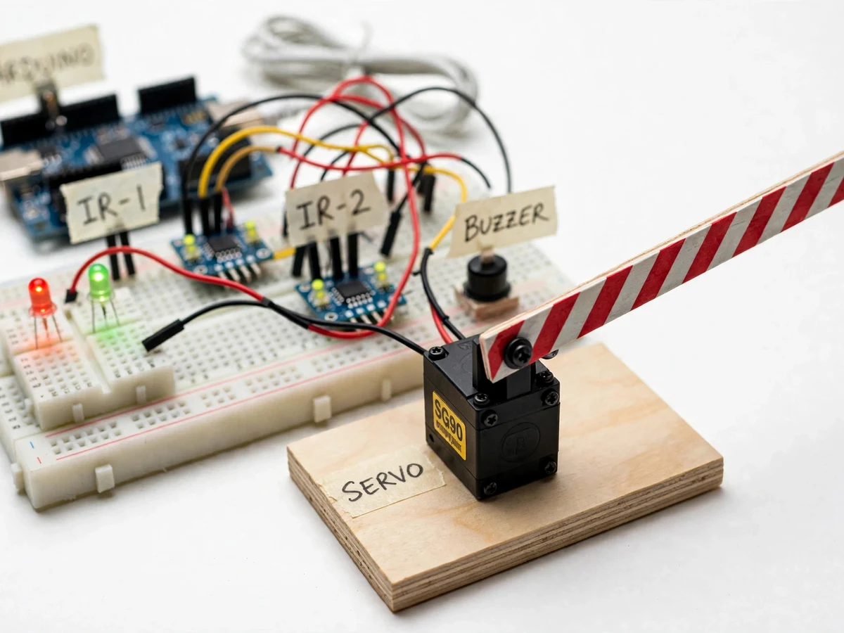
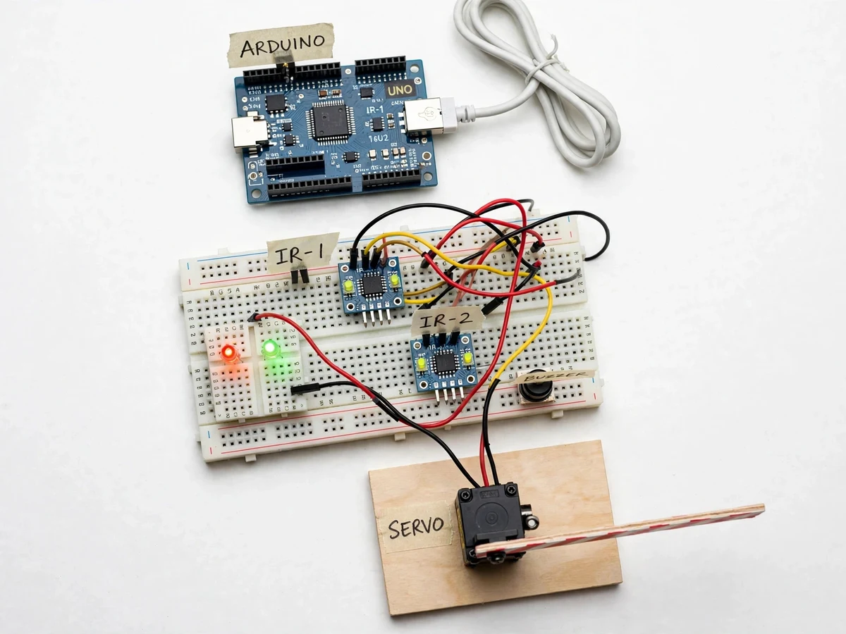
The problem
Level crossings remain one of the most accident-prone points on a railway network, and manually operated gates depend on a gateman noticing the train, reaching the gate in time, and closing it before road traffic enters the tracks. Human reaction time, fatigue, and unmanned crossings make this chain fragile. The engineering answer is automatic detection: sense the train's approach electronically, close the gate before it arrives, and reopen only after it has fully cleared. This project implements that exact loop at model scale — two reflective IR sensor modules watch the track on either side of the crossing, an Arduino UNO runs the detection and state-machine logic, an SG90 servo drives the gate arm, and red/green signal LEDs plus a buzzer warn road users. Because the prototype is built on a breadboard with visible wiring, every signal in the chain can be probed and explained.
Approach-side IR module detecting the arriving train body.
Follow the working sequence
How it works
- Two reflective IR sensor modules are mounted on the model track, one on each approach side at a fixed distance from the crossing point, with detection distance set via each module's onboard potentiometer.
- When a train body passes the arrival sensor, reflected IR crosses the module's comparator threshold and the Arduino registers an arrival event after a 200–500 ms debounce window (firmware-configurable).
- The controller switches the signal LEDs to red, starts the buzzer, and drives the SG90 servo from 0° to 90°, lowering the gate arm to the horizontal closed position.
- The gate stays closed while the departure-side sensor is untriggered — the firmware tracks crossing occupancy, not a single edge, so the gate cannot reopen under a slow or stopped train.
- Once the train's tail clears the departure sensor, the controller waits a short clearance delay, then returns the servo to 0°, switches the signal to green, and silences the buzzer.
- Arrival order (sensor 1 then 2, or the reverse) reveals the train's direction, but the safety logic is direction-agnostic: any confirmed arrival event closes the gate.
Tech stack:
- Arduino UNO (ATmega328P, 16 MHz)
- Embedded C · Arduino IDE
- Reflective IR sensor modules (LM358 comparator)
- SG90 micro servo motor
- 5 V buzzer · red/green signal LEDs
- Breadboard · jumper-wire prototyping
- Manual override push-button
- Regulated 5 V / 2 A power supply
| Parameter | Value |
|---|---|
| Sensing method | Reflective IR, dual modules (design) |
| Detection distance | 2–30 cm, adjustable via onboard potentiometer (design target) |
| Controller | Arduino UNO, ATmega328P @ 16 MHz |
| Gate actuator | SG90 micro servo, approx. 1.8 kg·cm stall torque (datasheet) |
| Gate travel | 0° (open) to 90° (closed), firmware-settable |
| Gate close time | Approximately 2–3 s from confirmed detection (design target) |
| Signal indication | 5 mm red + green LEDs |
| Audible alarm | 5 V active buzzer |
| Power | Regulated 5 V DC, 2 A (design) |
| Gate arm | Approximately 30 cm striped model arm (design) |
| Debounce window | 200–500 ms, firmware-configurable |
Project features
- [Bidirectional train sensing] Two IR sensor modules mounted on either side of the crossing detect the train's arrival and departure independently, so the controller works for trains approaching from either direction.
- [Automatic servo gate arm] An SG90 servo rotates a red-and-white striped gate arm between the open (vertical) and closed (horizontal) positions with no human operator involved.
- [Red/green signal indication] 5 mm trackside LEDs mirror the gate state: red while the gate is closed or moving, green when the road is clear to cross.
- [Audible warning buzzer] A 5 V active buzzer sounds during gate movement and stays on while the crossing is occupied by the train.
- [Debounce and occupancy state machine] Firmware filters sensor bounce with a configurable debounce window and holds the gate closed until the departure sensor confirms the train has fully cleared — a slow or halted train keeps the gate down.
- [Manual override push-button] A panel button forces the gate open or closed for demonstrations or while a sensor is being serviced.
- [Adjustable gate timing] Open/close servo angles and the clearance delay before reopening are firmware constants, tuned during calibration for the student's own model track.
What is included
- Assembled working prototype (Arduino, IR sensors, servo gate, signal LEDs, buzzer on breadboard and plywood base)
- Arduino firmware source with comments and calibration constants
- Circuit wiring diagram and connection table
- Sensor sensitivity calibration guide with a buyer-run test procedure
- Project report PDF (background, sensor theory, methodology, results template)
- PPT presentation for final review
- Viva Q&A preparation document (IR sensing, servo control, state machines)
Delivery timeline
- Typical build-and-test time is 10–14 working days from order confirmation; the report, PPT and viva Q&A ship with the prototype. Exact dates are confirmed in the quotation.
Support & explanation
- Build walkthrough call covering sensor calibration and the firmware constants; viva preparation support on IR sensing, servo control and state-machine logic; 15 days of post-delivery query support.
Limitations & prerequisites
- Reflective IR is sensitive to ambient infrared: direct sunlight or strong halogen lighting can false-trigger the sensors, so the build is designed for indoor demonstration — outdoor deployment would need modulated-IR sensing.
- Detection distance varies with the train surface: dark or matte bodies reflect less IR, so the 2–30 cm range is a design target that must be re-tuned with the onboard potentiometer for each model.
- This is a model-scale prototype, not railway-grade equipment: no redundancy, no fail-safe behavior and no safety certification — real level crossings use SIL-rated fail-safe systems.
- A power cut freezes the gate in its last position; the base build has no battery backup (available as an optional extension).
- Servo stall torque (approx. 1.8 kg·cm, datasheet) limits the arm to a lightweight approx. 30 cm model gate; wind or vibration can deflect it.
- A very fast or very short train could pass between sensor samples; the debounce and sensor-spacing procedure in the calibration guide addresses this for the model track.
- Dust or moisture on the sensor lenses degrades detection — the lenses need periodic cleaning.
Frequently Asked Questions
Why are two IR sensors used instead of one?
A single sensor can only say "something passed". Two sensors — one on each approach — let the controller distinguish arrival from departure and keep the gate closed until the train's tail has fully cleared the crossing. It also makes the logic direction-agnostic, so trains approaching from either side are handled identically.
Can sunlight cause false triggers?
Yes, and this is stated openly. Reflective IR modules react to ambient infrared, so strong sunlight or halogen lamps can false-trigger them. The build is designed for indoor demonstration, and the calibration guide sets the sensitivity for the demo room. Modulated-IR sensing is listed as future scope for outdoor use.
Why IR sensors and not ultrasonic or LDR?
IR obstacle modules are inexpensive, respond in milliseconds, and give a clean digital output the Arduino reads directly. Ultrasonics are slower and noisier at close range; LDRs depend on shadows and ambient light. The tradeoff is the ambient-IR sensitivity, which is owned openly in the limitations section.
Can this be installed on a real railway crossing?
No. This is a model-scale academic prototype. Real level crossings need fail-safe design, redundancy, battery backup and safety certification (SIL-rated systems) that a student build cannot claim. The project demonstrates the control principle — detect, warn, close, verify clearance — that real systems implement to railway standards.
What does the calibration involve?
The buyer runs a documented procedure: set each sensor's detection distance with its potentiometer for the model train, verify the debounce window, check the gate closes on arrival and reopens after the tail clears the departure sensor, then tune the servo angles and clearance delay. The report template records the student's own readings.
Is this project suitable for a final-year project?
Yes — for Electronics, Electronics & Telecommunication and related programs. It combines sensor interfacing, embedded C firmware with a state machine, and servo actuation into one demonstrable system, with honest limitations that give the viva real depth. Suitable for B.E./B.Tech final-year projects in Electronics, Electronics & Telecommunication.
Components & software requirements
- Arduino UNO (ATmega328P, 16 MHz)
- Embedded C · Arduino IDE
- Reflective IR sensor modules (LM358 comparator)
- SG90 micro servo motor
- 5 V buzzer · red/green signal LEDs
- Breadboard · jumper-wire prototyping
- Manual override push-button
- Regulated 5 V / 2 A power supply
Delivery information
Built-to-order project. Delivery timeline is shared after order confirmation based on current queue.
Support terms
Complete documentation, setup guide, and viva preparation included. Support for setup and explanation provided.
Download free synopsis (PDF)
Enter your name and email — the synopsis PDF downloads immediately. We may send occasional project updates; no spam, unsubscribe anytime.