
More project photos (2)
The problem
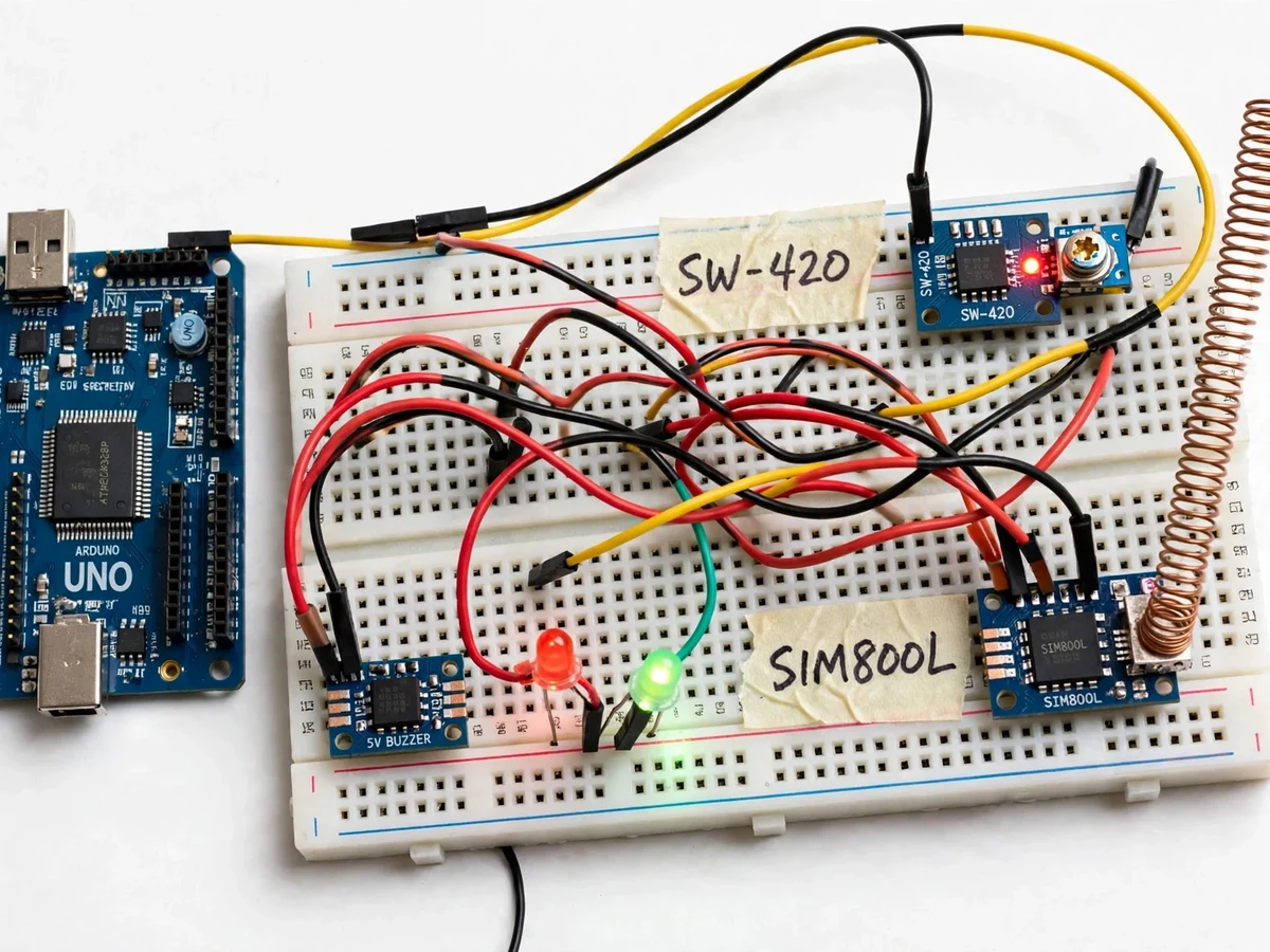
In earthquake-prone regions, even a few seconds of warning can matter — but professional seismic networks cost far more than a student can afford. This project builds an honest, low-cost alternative for study: an Arduino-based alarm that detects ground shaking above an adjustable threshold and alerts people immediately, both locally and by SMS. An SW-420 vibration sensor module watches the mounting surface; its digital output flips state when vibration crosses the threshold set on the module's onboard potentiometer. The Arduino then fires a 5 V buzzer and an alarm LED, and commands a SIM800L GSM module to send an SMS to the saved phone number. This is a vibration-threshold alarm, not a seismograph: it cannot measure magnitude, and it cannot predict earthquakes. What it does teach is real embedded-system design — sensor interfacing, threshold calibration, UART communication with AT commands, and GSM power-supply design — all of it solid viva material.
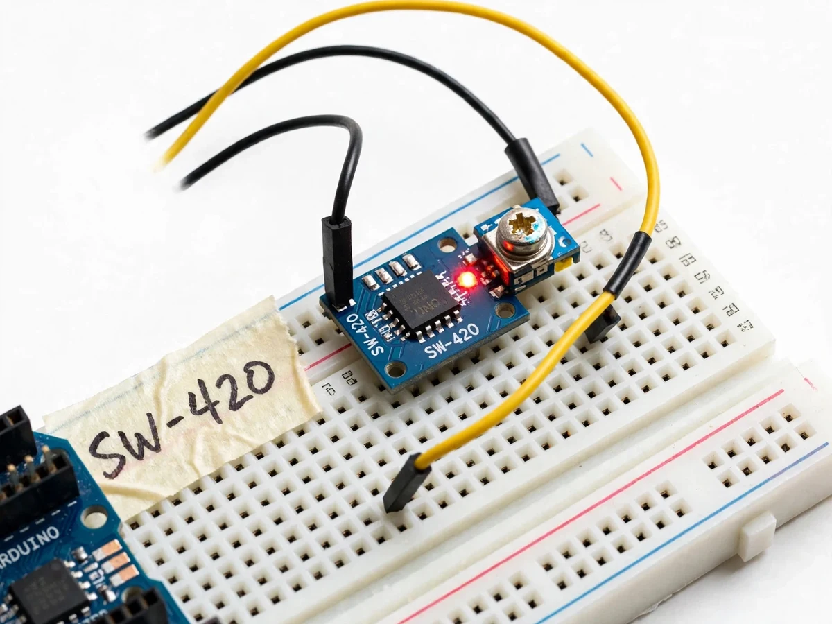
Spring-switch vibration module; the onboard LM393 comparator flips its digital output when shaking exceeds the potentiometer-set threshold.
Follow the working sequence
How it works
- The SW-420 module is fixed to the surface to be monitored and wired to a digital input pin, powered from 3.3 or 5 V DC. Its onboard LM393 comparator compares the spring-switch vibration signal against the threshold set on the module's potentiometer.
- On power-up, the Arduino initializes the SIM800L over UART, confirms network registration with AT commands, and enters a quiet monitoring state with a green status LED on.
- When vibration flips the sensor's digital output, the Arduino starts a short confirmation window (configurable, a fraction of a second) to reject single electrical glitches before committing to an alarm.
- If the signal holds, the alarm trips: the 5 V buzzer sounds, the red alarm LED lights, and the Arduino issues the SMS AT-command sequence to the SIM800L with the saved phone number.
- The SIM800L sends the text over the 2G GSM network. Delivery typically takes a few seconds and is network-dependent (expected); a confirmation tone then silences the local siren.
- The firmware enforces a 60-second re-arm delay (configurable, design target) so continuing aftershock waves cannot trigger repeat SMS messages.
- Sensitivity is calibrated with a documented knock-and-shake procedure: the potentiometer is turned until firm table knocks stay silent and hard shaking trips the alarm.
Tech stack:
- Arduino Uno (ATmega328P) + Arduino IDE
- SW-420 vibration sensor module (LM393 comparator)
- SIM800L GSM module + AT command set
- Embedded C / Arduino firmware (non-blocking design)
- UART serial interfacing (9600 baud, design target)
- 5 V buzzer + alarm LEDs (local alert hardware)
- LM2596-type buck converter (regulated GSM supply)
- Micro-SIM with SMS balance (2G network)
| Parameter | Value |
|---|---|
| Sensor module | SW-420 vibration switch, digital TTL output, LM393 comparator, sensitivity potentiometer, power + output LEDs |
| Sensor supply | 3.3–5 V DC (datasheet) |
| Sensor interface | 3 pins: VCC, GND, DO (digital output) |
| Sensor response | A few milliseconds (expected, design target) |
| GSM module | SIM800L, quad-band 850/900/1800/1900 MHz, 2G GSM/GPRS (datasheet) |
| GSM supply | 3.4–4.4 V DC regulated, up to 2 A peak during transmission bursts (datasheet) |
| GSM control | UART + AT command set (3GPP TS 27.007 / 27.005) |
| Controller | Arduino Uno (ATmega328P), 5 V, 16 MHz, 32 KB flash, 14 digital I/O (datasheet) |
| Local alert | 5 V buzzer + red alarm LED |
| SMS recipients | 1–3 saved numbers (configurable, design target) |
| SMS delivery time | Network-dependent, typically a few seconds (expected) |
| Re-arm delay | 60 s default, configurable (design target) |
| Power input | 5 V DC adapter rated 2 A (design target) |
Project features
- [SW-420 vibration sensing] The SW-420 module's digital output flips state when shaking exceeds the threshold dialed in on its onboard potentiometer, so the alarm ignores gentle knocks and trips on strong vibration. The module runs from 3.3–5 V DC and carries power and output indicator LEDs.
- [SMS alert via SIM800L] When the alarm trips, the Arduino sends AT commands over UART to the quad-band SIM800L GSM module (850/900/1800/1900 MHz per datasheet), which texts the saved number with a shake-detected message.
- [Local buzzer siren] A 5 V buzzer sounds and a red alarm LED lights the instant vibration is detected, so the warning still works where there is no mobile network coverage.
- [Adjustable sensitivity] The potentiometer on the sensor module sets the trip level during calibration — the build ships with a documented knock-and-shake test procedure for choosing it.
- [Debounced triggering] A software re-arm delay (60 s default, configurable) stops the alarm from firing repeat SMS alerts while shaking continues in waves.
- [Correct GSM power design] The SIM800L gets its own regulated 3.4–4.4 V feed (datasheet range) rated for 2 A transmission bursts — the classic GSM brown-out failure is designed out rather than debugged later.
- [Honest educational scope] The report states plainly what the build can and cannot do — a study-and-demonstration alarm, not a seismograph and not an earthquake predictor — which is exactly the scope examiners respect.
What is included
- Complete Arduino firmware sketch (calibrated threshold, debounce, AT-command SMS logic)
- Circuit and wiring diagram (sensor, Arduino, SIM800L, buzzer, separate GSM supply)
- Calibration procedure: knock-and-shake threshold setting with the module potentiometer
- Bill of materials with exact part names and typical vendors
- Project report PDF (background, circuit theory, GSM interfacing, calibration results, honest scope statement)
- PPT presentation for final review
- Viva Q&A document (vibration sensing, comparators, AT commands, GSM power design)
Limitations & prerequisites
- Threshold alarm, not a seismograph: it detects that shaking crossed a level — it cannot measure magnitude, epicenter or direction.
- Cannot predict earthquakes: no consumer vibration sensor gives advance warning; the alarm only reacts to shaking that has already started.
- Not certified safety equipment: a student-built demonstration, not a tested life-safety device — it must never be presented as protection-grade hardware.
- GSM needs an active micro-SIM with SMS balance, and the SIM800L is 2G-only: it works only where 2G GSM coverage still exists, so check your carrier's 2G availability first.
- SMS delivery latency is network-dependent (typically a few seconds, expected) and can stretch during disasters when networks congest.
- Strong non-seismic knocks — slammed doors, heavy traffic, construction — can trip the sensor if the threshold is set too low; calibration is mandatory.
- The module senses vibration at its mounting point only; a table-top build cannot represent the ground motion of a building.
Frequently Asked Questions
Can this project predict earthquakes?
No. It is a vibration-threshold alarm: the SW-420 module detects shaking that has already started, and the Arduino raises local and SMS alerts. No sensor at this level can give advance warning of an earthquake, and the report states this plainly — examiners respect an honest scope far more than a false prediction claim.
How does the SW-420 sensor work?
It is a spring-type vibration switch paired with an LM393 comparator on a small module. When shaking crosses the level set on the module's potentiometer, the digital output flips state and the Arduino reads it on a digital pin. Two LEDs show power and trigger status, and the module runs from 3.3–5 V DC.
Why does the SIM800L need a separate power supply?
The module's datasheet specifies 3.4–4.4 V with bursts up to 2 A during transmission; the Arduino's onboard regulator cannot supply that, and an underpowered GSM module resets the moment it tries to send. The build uses a dedicated regulated feed so the SMS goes out instead of the board browning out.
What happens when the alarm trips?
The buzzer sounds and the red LED lights within milliseconds of strong shaking, and the SIM800L texts the saved number over the 2G network. SMS delivery then depends on the mobile network — usually a few seconds, but it can be slower when towers congest during a real seismic event.
What do I need to keep SMS alerts working?
An active micro-SIM with SMS balance, and 2G GSM coverage from your carrier at the installation site — the SIM800L is a 2G-only module. The delivery includes a documented network-registration check using AT commands so all of this is confirmed before the demonstration.
Is this project suitable for a final-year project?
Yes — for Electronics, E&TC and Electrical programs. It combines sensor interfacing, comparator-based thresholding, UART and AT-command GSM control, and power-supply design into one demonstrable build. The honest scope (alarm, not seismograph) gives you a strong, defensible viva story — and the calibration process gives you real measured results to discuss.
Components & software requirements
- Arduino Uno (ATmega328P) + Arduino IDE
- SW-420 vibration sensor module (LM393 comparator)
- SIM800L GSM module + AT command set
- Embedded C / Arduino firmware (non-blocking design)
- UART serial interfacing (9600 baud, design target)
- 5 V buzzer + alarm LEDs (local alert hardware)
- LM2596-type buck converter (regulated GSM supply)
- Micro-SIM with SMS balance (2G network)
Delivery information
Built-to-order project. Delivery timeline is shared after order confirmation based on current queue.
Support terms
Complete documentation, setup guide, and viva preparation included. Support for setup and explanation provided.
Download free synopsis (PDF)
Enter your name and email — the synopsis PDF downloads immediately. We may send occasional project updates; no spam, unsubscribe anytime.