
More project photos (3)
The problem
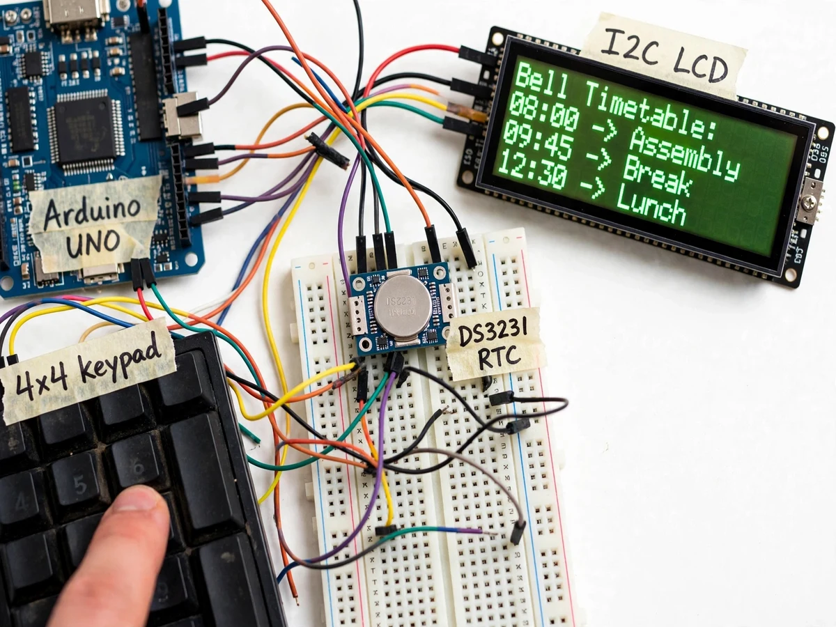
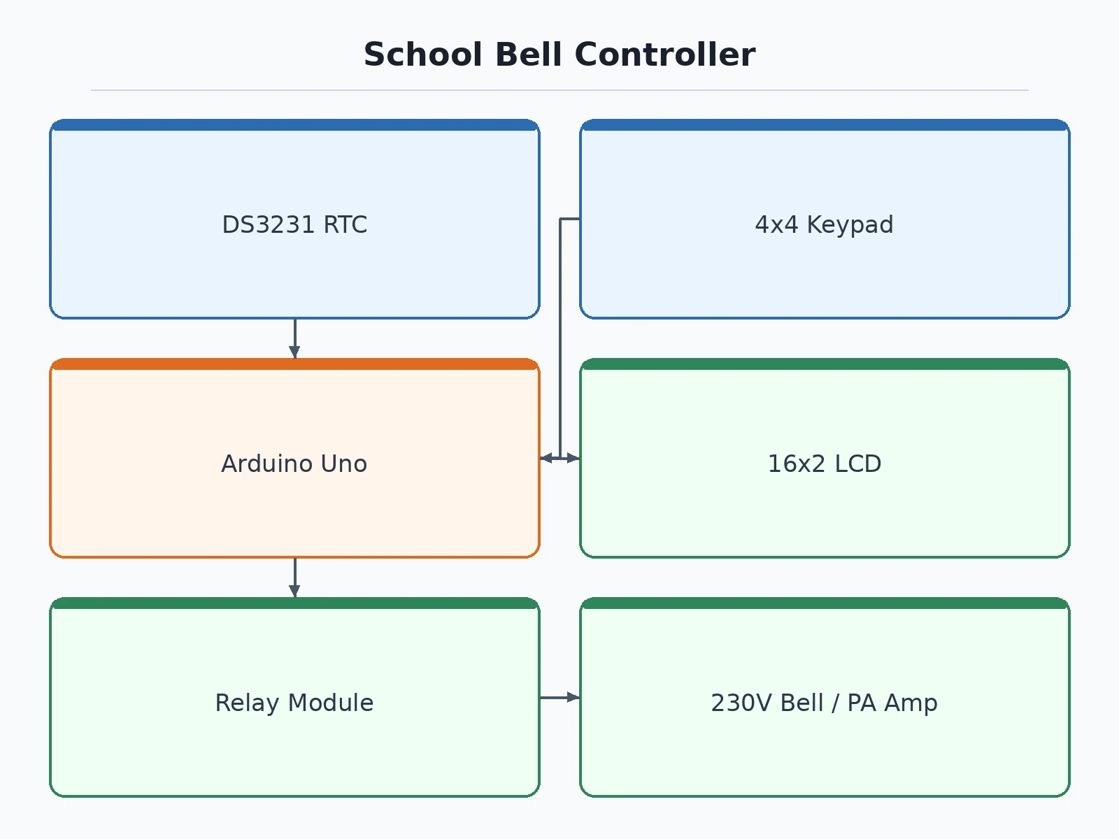
In most schools, class-change bells are still rung by hand: someone watches a wall clock and pulls a switch at the start of every period, break, and assembly. A minute's delay in one period propagates through the whole day, bells get skipped when the person is busy elsewhere, and no record exists of when bells actually rang. This project automates the job properly. It is an Arduino-based bell controller built around a DS3231 real-time clock — a temperature-compensated RTC accurate to ±2 ppm (datasheet), so the schedule does not drift even across months. The controller stores a weekly timetable in EEPROM, compares the live time against it every second, and fires a relay output at each programmed bell: period change, short break, lunch, assembly, dismissal. That relay either rings a conventional 230 V AC electric bell directly, or sends a dry-contact trigger into the school's PA amplifier line input so the bell tone plays through the campus speakers. A 16x2 LCD always shows the clock and the next scheduled bell, and a keypad lets staff edit the timetable without touching code. Normal-day, exam-day, half-day and holiday modes handle the real school calendar.
DS3231 temperature-compensated real-time clock set once at commissioning; the CR2032 cell holds time through every power cut.
Follow the working sequence
How it works
- The DS3231 RTC is set once from a PC clock during commissioning; from then on it holds time on its CR2032 cell through every power cut, read by the Arduino over I2C every second.
- The bell timetable (day, hour, minute, duration, mode) lives in EEPROM; at startup the firmware loads today's schedule and selects normal/exam/half-day/holiday mode from the keypad or its saved default.
- Every second the Arduino compares the RTC time against the schedule at one-second resolution, with a match window that prevents double-firing on the same minute.
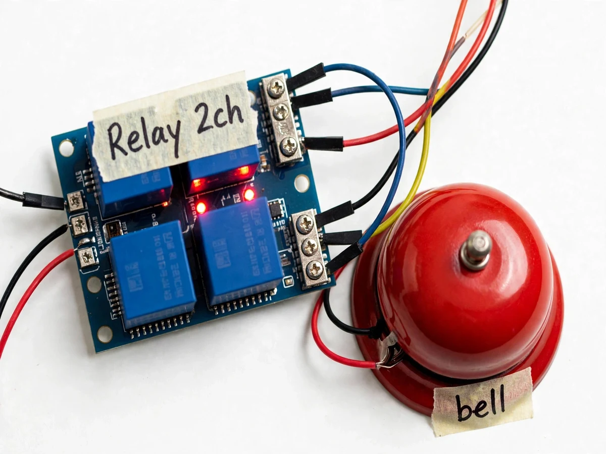
- On a match, the firmware energizes the relay for the programmed ring duration (typical 5 s, adjustable 1–30 s) — either switching the 230 V bell or closing the PA trigger contact — and logs the event on the LCD.
- The LCD shows live time, the active mode, and the next bell (e.g. "NEXT 11:40 BRK"), refreshing the countdown every minute.
- Staff edit bell times through the keypad menu (add, change, delete entries, switch modes); changes write straight to EEPROM and take effect without re-uploading firmware.
- A manual-bell push button rings on demand for emergencies, with hold-for-ring logic so a stuck button cannot leave the bell on.
Tech stack:
- Arduino UNO (ATmega328P)
- DS3231 RTC module (I2C, CR2032 backup)
- Embedded C (Arduino IDE)
- 4x4 matrix keypad
- 16x2 LCD with I2C backpack
- SRD-05VDC relay module (optoisolated)
- 230 V AC electric bell / PA line trigger
| Parameter | Value |
|---|---|
| Controller | Arduino UNO, ATmega328P at 16 MHz (datasheet) |
| RTC module | DS3231: ±2 ppm accuracy, 0–40 °C; CR2032 keeps time through power cuts (datasheet) |
| Schedule storage | Up to 40 bell entries/day in onboard EEPROM; survives power loss (firmware design) |
| Bell duration | 1–30 s per ring, programmable; typical 5 s (firmware) |
| Relay output | SRD-05VDC module: 10 A / 250 VAC contacts, optoisolated coil (datasheet) |
| PA interface | Dry-contact closure to amplifier line/mic or trigger input via screw terminal; passive contact, no voltage injected (design) |
| Display | 16x2 LCD with I2C backpack; shows time, mode and next bell with countdown (expected) |
| User input | 4x4 matrix keypad for menu editing; dedicated manual-bell push button |
| Schedule modes | Normal day / exam day / Saturday half-day / holiday-skip, keypad-selectable (firmware) |
| Power | 5 V USB or 7–12 V barrel jack (datasheet); bell circuit fused and wired separately (installation) |
Project features
- [RTC scheduling with ±2 ppm accuracy] A DS3231 temperature-compensated real-time clock (±2 ppm from 0–40 °C, datasheet) holds schedule time through power cuts on its CR2032 backup cell, so the controller never needs re-clocking after an outage.
- [EEPROM timetable storage] Up to 40 daily bell entries are stored in the Arduino's onboard EEPROM — schedules survive power loss, and are edited through the keypad menu rather than by re-uploading firmware.
- [Dual output: mains bell or PA trigger] A relay module (SRD-05VDC, 10 A / 250 VAC contacts, datasheet) either rings a standard 230 V AC electric bell directly or closes a dry contact into the school's PA amplifier line/mic input — the mode is chosen at installation.
- [Weekly schedule modes] Four stored timetables — normal day, exam day, Saturday half-day, and holiday skip — are selectable from the keypad, so the controller handles the real school calendar without daily reprogramming.
- [16x2 LCD status display] An I2C 16x2 LCD continuously shows the current time, the active schedule mode, and the next bell with its countdown, so the unit is demonstrable and serviceable at a glance.
- [Keypad editing plus manual bell] A 4x4 matrix keypad edits bell times through on-screen menus, and a dedicated push button rings the bell manually for emergencies or unscheduled announcements.
- [Safe mains isolation] Control logic and the 230 V bell circuit are galvanically isolated through the relay; the bell side is fused and wired on labelled screw terminals, and the guide requires mains connections to be made or checked by an electrician.
What is included
- Assembled controller: Arduino, DS3231 RTC, relay module, 16x2 LCD, 4x4 keypad, manual-bell button, fused bell/PA output terminals in an enclosure
- Complete firmware source code (schedule engine, keypad menu, EEPROM layout documented)
- Wiring diagram with mains-isolation and earthing notes
- Component list with datasheet references
- Timetable programming guide written for non-technical school staff
- Electric-bell and PA-interface connection guides (mode chosen at installation)
- Project report PDF (background, RTC theory, scheduling design, testing)
- PPT presentation for final review
- Viva Q&A preparation document (RTC drift math, relay ratings, EEPROM wear, mains safety)
Limitations & prerequisites
- Mains wiring to the 230 V bell must be done or verified by a qualified electrician; bench demos use a low-voltage indicator on the relay output for safety.
- The ±2 ppm RTC accuracy is a datasheet value for the DS3231, not a measured figure — long-term drift is not measured in this build.
- One relay switches one bell or one PA trigger; schools with multiple zones need one unit per zone (listed as an extension).
- Holiday dates are entered manually in holiday-skip mode; there is no automatic academic-calendar sync.
- EEPROM supports ~100,000 write cycles per cell (datasheet); timetable edits are infrequent and the firmware minimizes writes, so this is not a concern for scheduling use.
- The PA interface is a dry-contact trigger, not an audio amplifier — it assumes the school already has a PA amplifier with a line/mic or trigger input.
Frequently Asked Questions
Why the DS3231 and not the cheaper DS1307?
Schedule drift is the whole point of this project. The DS1307 is an uncompensated crystal RTC that can drift a minute or more per month with temperature changes; the DS3231 is temperature-compensated and rated ±2 ppm (datasheet) — about 0.17 seconds per day worst case — so bells stay on schedule for a full term without correction. The price difference is small, and the accuracy story is strong viva material.
Is it safe to connect a 230 V bell to a student project?
Only through the design's isolation: the relay module keeps the Arduino's 5 V logic galvanically separate from the bell circuit, the bell side is fused and wired on labelled screw terminals, and the installation guide requires mains wiring to be done or checked by an electrician. During bench demonstrations the relay output drives a low-voltage indicator instead of the mains bell.
Can it ring through the school's existing PA system?
Yes. In PA mode the relay closes a dry contact wired to the amplifier's trigger or line/mic input instead of switching mains. The contact is a passive switch that carries no voltage of its own, so it cannot overload the amplifier input; the trigger wiring is documented separately from the mains-bell wiring.
How many bells can it schedule and how are they edited?
Up to 40 entries per day in EEPROM, each with a time, ring duration (1–30 s) and schedule mode. Staff edit them through the keypad and LCD menus (add, change, delete, switch modes), with changes saved to EEPROM immediately — no computer or firmware re-upload is needed after commissioning.
What happens during a power cut?
The DS3231 keeps time on its CR2032 backup cell and the timetable stays in EEPROM, so when power returns the controller resumes the correct schedule automatically. Bells scheduled during the outage itself are missed — documented as a limitation; an optional battery-backed supply for the controller is listed as an extension.
Is this project suitable for a final-year project?
Yes — for Electronics, Electrical and IoT programs. It combines a real timing problem (RTC selection and drift math), embedded scheduling logic, relay and mains-isolation safety, a staff-usable interface, and an installation a real school could use — all of it explainable end to end.
Components & software requirements
- Arduino UNO (ATmega328P)
- DS3231 RTC module (I2C, CR2032 backup)
- Embedded C (Arduino IDE)
- 4x4 matrix keypad
- 16x2 LCD with I2C backpack
- SRD-05VDC relay module (optoisolated)
- 230 V AC electric bell / PA line trigger
Delivery information
Built-to-order project. Delivery timeline is shared after order confirmation based on current queue.
Support terms
Complete documentation, setup guide, and viva preparation included. Support for setup and explanation provided.
Download free synopsis (PDF)
Enter your name and email — the synopsis PDF downloads immediately. We may send occasional project updates; no spam, unsubscribe anytime.