
More project photos (2)
The problem
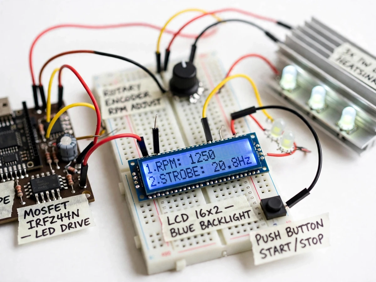
Measuring the speed of a rotating fan, motor or shaft without touching it is a genuine instrumentation problem: contact tachometers need physical access and reflective stickers, handheld optical tachometers only give a reading with no insight into the mechanism, and commercial digital stroboscopes cost far more than a student budget allows. The stroboscopic principle solves the measurement elegantly — a rotating object illuminated by brief flashes at exactly its rotation frequency appears stationary, because each flash catches it in the same angular position. This project turns that principle into a student-built instrument: an Arduino Nano generates the flash timing, a MOSFET switches a 3x1W white LED array on an aluminium heatsink, a rotary encoder and step buttons set the flash frequency over a design-target range of 1-200 Hz (60-12,000 RPM), and a 16x2 LCD shows flash frequency and computed RPM (RPM = flash frequency x 60). The freeze is a visual null measurement, so the build also teaches aliasing: motion freezes at integer sub-multiples too, and the calibration procedure shows how to resolve the true speed.
Aims the LED array at the shaft and sweeps the encoder to the freeze point.
Follow the working sequence
How it works
- The Arduino Nano configures Timer1 in CTC mode: a compare-match interrupt fires at twice the desired flash rate (for equal on/off timing) and toggles the MOSFET gate pin for a short pulse each cycle.
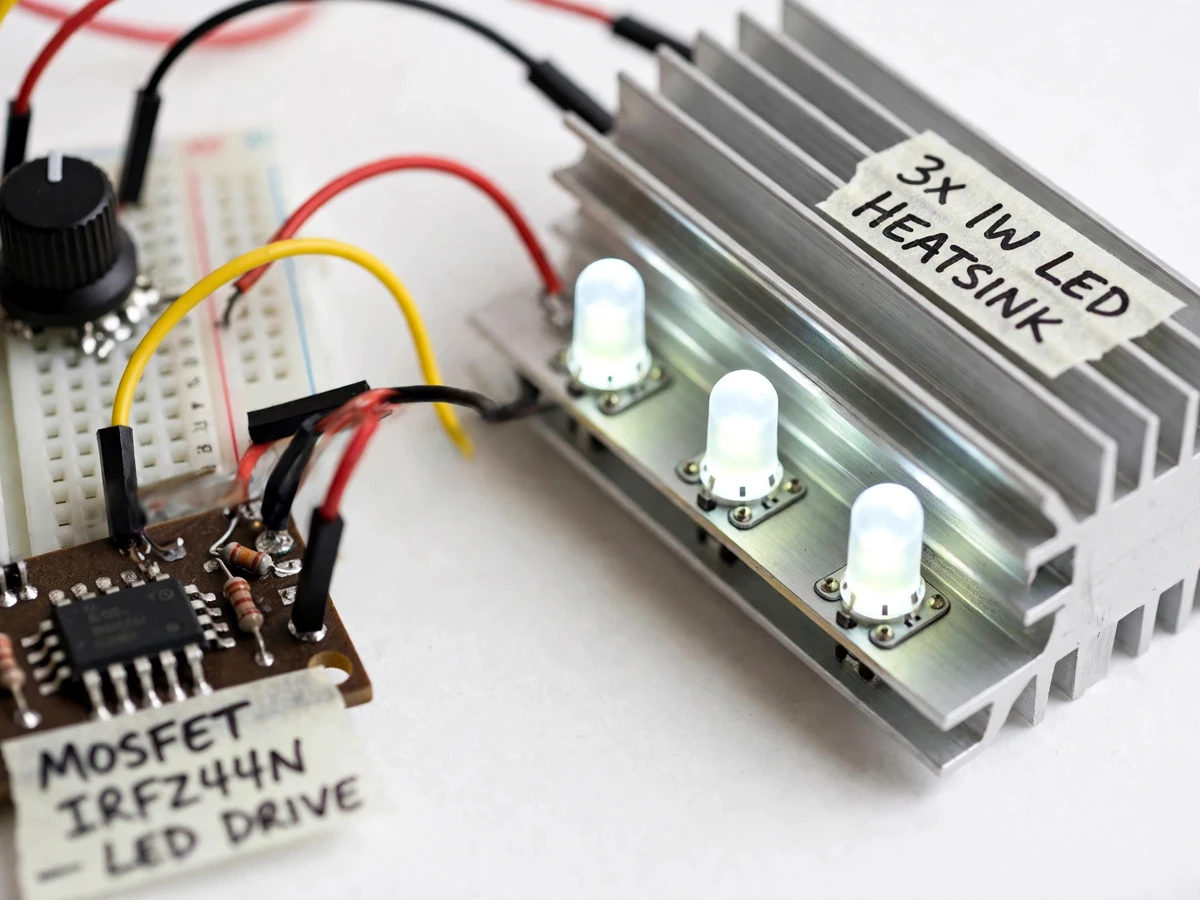
- The logic-level MOSFET switches the 12V rail through the 3x1W white LED array with current-limiting resistors, producing brief, intense flashes on the aluminium heatsink.
- The student aims the LED array at the rotating fan or shaft and turns the rotary encoder until the blades or shaft mark appear stationary — the freeze point.
- At freeze, flash frequency equals rotation frequency (or an integer sub-multiple); halving the frequency and checking the image stays frozen confirms which, per the calibration guide.
- Firmware computes RPM as flash frequency x 60 and updates the 16x2 LCD with both values in real time.
- The fine (1 Hz) and coarse (10 Hz) step buttons nudge the frequency to lock the freeze precisely; the encoder sets the approximate region first.
- For the report, the student repeats the measurement at the sub-multiple freezes and records the readings following the included procedure, documenting the method honestly.
Tech stack:
- Arduino Nano (ATmega328P)
- 3x1W white LED array on aluminium heatsink
- IRLZ44N logic-level MOSFET driver
- Rotary encoder + 16x2 LCD
- Current-limiting resistor network
- Arduino IDE (C/C++ firmware)
- 12V DC regulated adapter
- Perfboard/breadboard prototype assembly
| Parameter | Value |
|---|---|
| Flash frequency range | Design target 1-200 Hz, adjustable |
| Measurable RPM range | Design target 60-12,000 RPM (RPM = flash frequency x 60) |
| LED array | 3 x 1W high-brightness white LEDs, aluminium heatsink |
| LED luminous output | Typically 100-120 lm per LED (typical value, not a measured claim) |
| Controller | Arduino Nano (ATmega328P, 16 MHz) |
| Frequency control | Rotary encoder (smooth sweep) + 1 Hz / 10 Hz step buttons |
| Display | 16x2 character LCD: flash frequency + computed RPM |
| MOSFET driver | Logic-level N-channel (IRLZ44N class), switching 12V |
| Power | 12V DC regulated adapter (design approximately 1-1.5 A) |
| Flash pulse | Short pulse per cycle, design target 1-5% duty cycle (buyer-adjustable in firmware) |
Project features
- [Adjustable flash frequency] A rotary encoder sweeps the flash rate smoothly across the design-target range of 1-200 Hz, with push buttons for fine (1 Hz) and coarse (10 Hz) steps to lock the frozen image precisely.
- [Direct RPM readout] The 16x2 LCD continuously shows the set flash frequency and the computed RPM (flash frequency x 60), so the reading is immediate once the motion freezes.
- [High-brightness LED array] Three 1W white LEDs on an aluminium heatsink provide the short, intense flashes needed for a clean freeze; a logic-level MOSFET switches the 12V rail with current-limiting resistors.
- [Timer-driven firmware] Flash timing is generated by the Arduino Nano's hardware Timer1 compare interrupt, not delay loops, so the frequency stays stable while the encoder and LCD are serviced.
- [Sub-multiple freeze demonstration] Motion freezes at integer sub-multiples of the true frequency as well (for example an 1800 RPM shaft freezes at 30 Hz, 15 Hz and 10 Hz); the included procedure shows how to confirm the true RPM.
- [Buyer-run calibration procedure] A step-by-step guide uses a marked shaft and, where available, a reference tachometer to verify the freeze point and document the achieved accuracy in the student's own report.
- [Low-voltage safe build] The prototype runs entirely from a 12V DC regulated adapter; no mains wiring appears on the student build, and the LED array is heatsink-mounted with duty-cycle guidance.
- [Viva-ready commented firmware] The Arduino code is fully commented around timer configuration, MOSFET drive, encoder handling and the RPM computation, so every design choice can be defended.
What is included
- Working digital stroboscope prototype (assembled, firmware loaded and tested at build bench)
- Arduino Nano firmware source code (commented, Timer1-based flash generation)
- Circuit and wiring diagram with exact part numbers and resistor sizing notes
- Component list (controller, LEDs, heatsink, MOSFET, encoder, LCD, adapter)
- Buyer-run frequency calibration and sub-multiple verification procedure
- Project report PDF (stroboscopic theory, design, methodology, measurement procedure)
- PPT presentation for final review
- Viva Q&A preparation document (stroboscopic principle, aliasing, timer interrupts, MOSFET driving)
Limitations & prerequisites
- Motion also freezes at integer sub-multiples of the true frequency, so the student must run the included half-frequency verification; an unverified reading can be off by an integer factor.
- High ambient light washes out the flash — demonstrations need dimmed room light or the LED array aimed within roughly 0.5-1 m of the target.
- Speeds above approximately 12,000 RPM exceed the design flash range; below approximately 60 RPM the freeze is found via the sub-multiple technique and takes patience.
- The 1W LEDs must stay on the aluminium heatsink with ventilation; the build guide sets duty-cycle limits because the array cannot run indefinitely at full flash duty without airflow.
- This is a visual-null method, not an instrument-grade tachometer: reading accuracy depends on the operator's freeze-point judgment, expected within a few RPM at low speeds and degrading with speed.
- No reference verification is built in; cross-checking against a contact tachometer (where available) is the buyer's procedure, not a shipped feature.
Frequently Asked Questions
What is the stroboscopic principle behind it?
When a rotating object is lit by flashes at exactly its rotation frequency, each flash catches it in the same angular position and it looks frozen. The flash frequency then equals the rotation frequency, and RPM is simply that frequency multiplied by 60 — a visual null measurement with no contact needed.
Which controller is used and why?
An Arduino Nano (ATmega328P). The flash timing comes from its hardware Timer1 compare interrupt, which keeps the frequency stable and jitter-free while the firmware simultaneously reads the encoder and updates the LCD — a genuine timer-interrupt design, not delay loops.
What power supply is needed?
A 12V DC regulated adapter (design approximately 1-1.5 A). The entire prototype is low-voltage; there is no mains wiring on the student build, and the LED array is current-limited through resistors with heatsink mounting. The Nano's 5V logic is kept separate from the 12V switching rail so the LED drive cannot disturb the flash timing.
How do you know the freeze shows the true RPM and not a sub-multiple?
Motion freezes at integer sub-multiples too. The calibration procedure says: halve the flash frequency — if the image stays frozen, you were at a multiple. Working down to the lowest frequency that still freezes gives the true rotation rate, and the guide documents each step for the report.
What will I receive with the project?
The working prototype, commented Arduino firmware, wiring diagram with part numbers, component list, the calibration/verification procedure, project report PDF, review PPT and viva Q&A document — the full student kit, built to order. Firmware ships as commented source, so every timer and MOSFET-driver choice can be explained in the viva.
Is this project suitable for a final-year project?
Yes — for Electronics & Telecommunication, Electrical and Instrumentation programs. It demonstrates timer-based embedded firmware, power-electronics driving (MOSFET, LED current limiting), the stroboscopic measurement principle with honest aliasing analysis, and a documented calibration procedure that puts real verified measurements into the student's report. Suitable for B.E./B.Tech final-year projects in Electronics & Telecommunication, Electrical and Instrumentation Engineering.
Components & software requirements
- Arduino Nano (ATmega328P)
- 3x1W white LED array on aluminium heatsink
- IRLZ44N logic-level MOSFET driver
- Rotary encoder + 16x2 LCD
- Current-limiting resistor network
- Arduino IDE (C/C++ firmware)
- 12V DC regulated adapter
- Perfboard/breadboard prototype assembly
Delivery information
Built-to-order project. Delivery timeline is shared after order confirmation based on current queue.
Support terms
Complete documentation, setup guide, and viva preparation included. Support for setup and explanation provided.
Download free synopsis (PDF)
Enter your name and email — the synopsis PDF downloads immediately. We may send occasional project updates; no spam, unsubscribe anytime.