
More project photos (2)
The problem
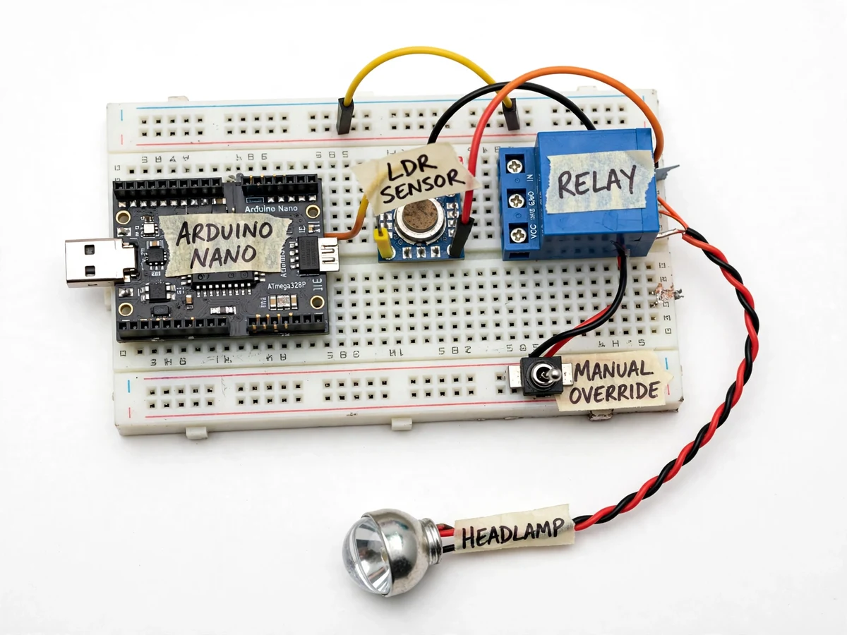
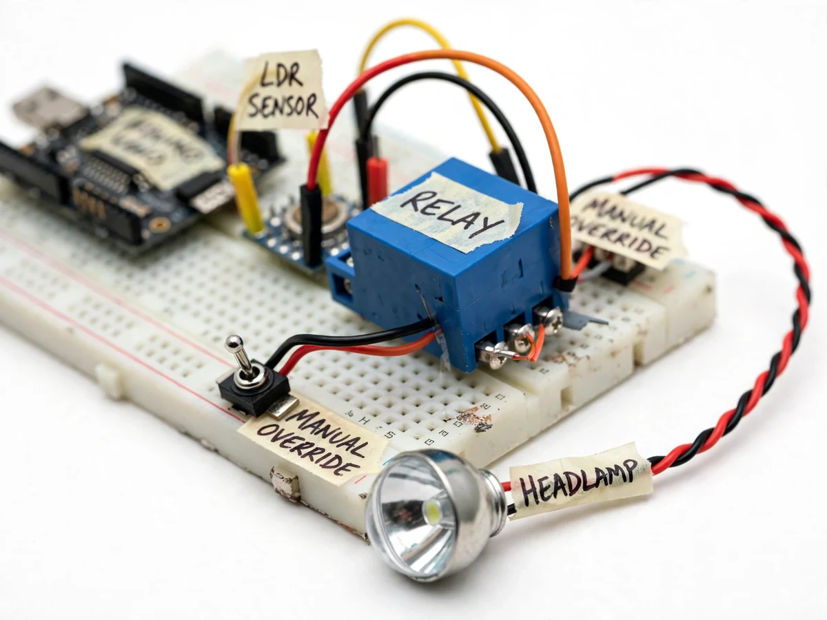
High-beam glare from oncoming vehicles is one of the most common night-driving complaints on Indian highways and rural roads, and much of it is accidental — drivers simply forget to dip their beams in time. Manual dimming depends on reaction and discipline, so it fails exactly when it matters most. This project automates that one decision: an LDR light sensor watches the light arriving at the vehicle, an Arduino Nano decides whether an oncoming headlight is present, and a relay switches the headlamp between high and low beam without the driver touching anything. A hysteresis band in the firmware keeps the relay from chattering at the threshold, and a manual override switch lets the driver take control at any moment. The bench prototype demonstrates the complete sense–decide–actuate loop with a model headlamp, and the report documents how the same circuit maps onto a real vehicle's headlamp wiring.
Light-dependent resistor in a voltage divider; brighter incoming light gives a higher ADC reading.
Follow the working sequence
How it works
- The LDR forms a voltage divider with a fixed resistor; the Arduino Nano reads the divider voltage on an analog pin, so brighter incoming light gives a higher ADC value.
- Every loop, the firmware compares the reading against two thresholds: if it rises above the high threshold, the relay is energized and the headlamp drops to low beam; it returns to high beam only when the reading falls below the lower threshold (hysteresis).
- A second, longer-term reading tracks ambient light; when the ambient level indicates daytime, the dimming logic is held off so daylight flicker never triggers a dip.
- The manual override toggle is read on a digital pin with debouncing; when forced high by the driver, it bypasses the automatic logic and holds high beam until released.
- The Arduino drives the relay module through a transistor or the module's built-in driver stage; an LED on the module shows the energized state for the demo.
- For calibration, the student shines a flashlight at the LDR while watching serial-monitor readings, then sets the two thresholds to bracket typical oncoming-headlight intensity versus night ambient.
Tech stack:
- Arduino Nano (ATmega328P)
- LDR sensor module (CdS photoresistor · LM393 comparator)
- 5V single-channel relay module
- Arduino IDE (C/C++ firmware)
- Voltage divider + threshold logic
- Toggle switch (manual override)
- Serial Monitor (calibration readouts)
- LED headlamp model (bench demonstration)
| Parameter | Value |
|---|---|
| Controller | Arduino Nano, ATmega328P (5 V logic) |
| Light sensor | LDR module, analog output to ADC pin A0 |
| Switch element | 5 V relay module, ~10 ms operate/release (datasheet value) |
| Relay contact rating | Approximately 10 A / 250 VAC (module datasheet) |
| Relay electrical life | Approximately 100,000 operations (datasheet design target) |
| LDR response | Rise ~30 ms, decay ~40 ms (component datasheet typical) |
| Dim/restore thresholds | Configurable in firmware (buyer-run calibration procedure) |
| Manual override | Toggle switch, independent of sensing logic |
| Prototype supply | 5 V DC (USB or adapter); headlamp model on low-voltage LED |
Project features
- [Automatic beam dimming] When the LDR detects bright incoming light above the set threshold, the Arduino drives the relay to switch the headlamp from high beam to low beam automatically, restoring high beam once the light level falls back.
- [Hysteresis band in firmware] Separate switch-on and switch-off thresholds with an adjustable dead band stop the relay from flickering when the light level hovers at the trip point — the classic fix for sensor chatter, implemented in code.
- [Manual override switch] A toggle switch wired in parallel lets the driver force high beam at any time; the override path is independent of the sensing logic so it works even if the sensor misbehaves.
- [Day/night awareness] Ambient light level is read continuously; the dimming logic only engages after dark so passing shadows or daylight driving don't trigger false dips.
- [Relay-based load switching] A 5V single-channel relay module switches the headlamp circuit with proper NO/NC contact wiring, opto-isolated from the Arduino's 5V logic side.
- [Threshold calibration in code] Trip levels are named constants in the firmware with a commented calibration procedure, so the student can tune sensitivity during the demo using a flashlight as a stand-in for oncoming traffic.
- [Bench headlamp demonstration model] The prototype drives a model headlamp bulb so the full sensing-to-switching behaviour is visible on the bench without touching a real vehicle.
What is included
- Working bench prototype: Arduino Nano, LDR sensor module, relay module, model headlamp, manual override switch
- Complete firmware (Arduino sketch) with hysteresis, day/night logic and debounced override
- Wiring diagram and breadboard layout
- Calibration procedure using a flashlight and the serial monitor
- Component list with sourcing notes
- Project report PDF (background, design, methodology, observations)
- PPT presentation for final review
- Viva Q&A preparation document (sensors, hysteresis, relays, isolation)
Limitations & prerequisites
- The prototype is a bench demonstration model; fitting it to a real vehicle's headlamp circuit and 12 V electrical system is installation work the buyer handles with a qualified mechanic — it is not included.
- The LDR responds to total light, not to "an oncoming vehicle" specifically — bright streetlights or reflective signs can influence the reading, which is why threshold calibration is part of the procedure.
- Relay contact life is a datasheet design target (approximately 100,000 operations); the buyer runs the switching during their own demonstration, so no lifetime testing is claimed here.
- LDR spectral response peaks near green (~540 nm) while headlamps are warmer/cooler, so sensitivity to different headlight types is approximate and calibration-dependent.
- Dimming reacts in tens of milliseconds (LDR + relay time); it assists the driver, it is not a certified automotive safety device.
- The headlamp model in the prototype is a low-voltage LED stand-in, not a real 55 W halogen/LED automotive bulb.
Frequently Asked Questions
Is this project suitable for a final-year project?
Yes — for Electronics & Telecommunication and Electrical Engineering. It demonstrates sensors (LDR, ADC), signal conditioning, hysteresis control logic, relay interfacing with isolation, and a complete sense–decide–actuate loop around a real automotive problem.
Which controller is used?
An Arduino Nano (ATmega328P). It was chosen because the logic needs only one analog input, one digital input and one relay output — no wireless or heavy computation, so a Nano is the honest fit.
Why does it use hysteresis instead of a single threshold?
With one threshold, light levels hovering at the trip point make the relay chatter on and off rapidly, which wears the contacts and looks broken. Two thresholds — one to dip, a lower one to restore — create a dead band that keeps switching clean.
Can the manual override be trusted?
Yes. It is wired as an independent priority path in the firmware, so the driver can always force high beam regardless of what the sensor logic is doing — the same safety principle real vehicles need.
Can it be fitted to my actual car or bike?
The report includes a wiring note for a 12 V vehicle headlamp circuit, but installation on a real vehicle is not included — it should be done with a qualified mechanic, and local regulations on headlamp modifications apply.
What power supply does the prototype need?
The bench prototype runs on 5 V DC from USB or a standard adapter; only the model headlamp is powered through the relay contacts, so nothing mains-connected is involved. Suitable for B.E./B.Tech final-year projects in Electronics & Telecommunication and Electrical Engineering.
Components & software requirements
- Arduino Nano (ATmega328P)
- LDR sensor module (CdS photoresistor · LM393 comparator)
- 5V single-channel relay module
- Arduino IDE (C/C++ firmware)
- Voltage divider + threshold logic
- Toggle switch (manual override)
- Serial Monitor (calibration readouts)
- LED headlamp model (bench demonstration)
Delivery information
Built-to-order project. Delivery timeline is shared after order confirmation based on current queue.
Support terms
Complete documentation, setup guide, and viva preparation included. Support for setup and explanation provided.
Download free synopsis (PDF)
Enter your name and email — the synopsis PDF downloads immediately. We may send occasional project updates; no spam, unsubscribe anytime.