
More project photos (2)
The problem
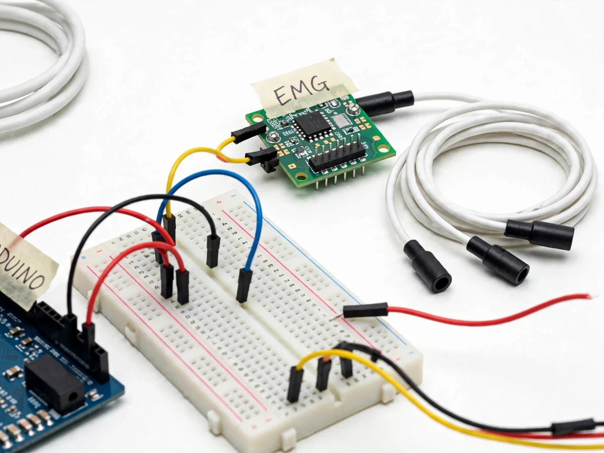
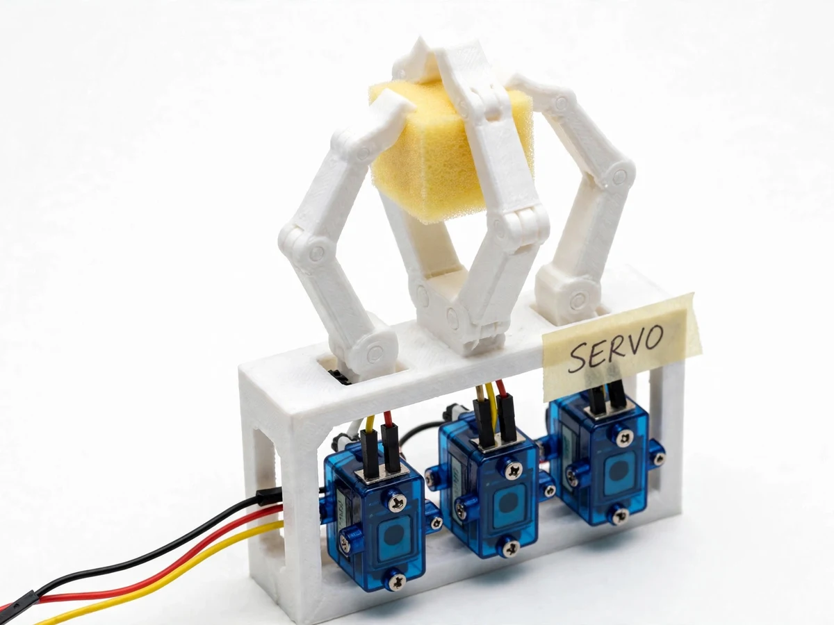
Conventional robotic grippers are driven by buttons, joysticks or pre-programmed sequences — all of which keep the user's hands tied to a controller. For assistive devices and prosthetics, the more natural interface is the user's own muscle activity: surface electromyography (sEMG) picks up the tiny electrical signals generated when a muscle contracts, and those signals can open or close a gripper directly. Working with real biosignals is the genuine engineering challenge here — electrode placement, skin contact, motion artifacts and person-to-person signal variation make any fixed factory threshold useless, so a working system must calibrate to its user and reject flicker near the trigger point. This project tackles exactly that: a MyoWare-style EMG module captures the forearm flexor signal, an Arduino Uno maps it through a calibrated threshold with hysteresis, and three SG90 servos drive a 3D-printed 3-finger gripper. The result is a working human-machine interface — flex to grip, relax to release — with the full calibration and wiring procedure documented so the build is genuinely reproducible.
Flexor contraction generates the microvolt-level EMG signal the electrodes pick up.
Follow the working sequence
How it works
- Three disposable snap electrodes are placed on the forearm — two over the flexor muscle belly a few centimetres apart, and one reference electrode on a bony area such as the elbow.
- The EMG module's front end picks up the microvolt-level muscle signal, filters and rectifies it, and outputs a smooth envelope voltage from 0 V up to the supply voltage (datasheet 0–Vs) that tracks contraction strength.
- The Arduino reads this envelope on an analog input (10-bit ADC, 0–1023 counts over 0–5 V) at an expected ~100 Hz sampling loop and applies a light moving-average filter.
- A guided calibration routine records the envelope during rest and during a hard flex; the midpoint becomes the trigger threshold with a hysteresis band, stored in EEPROM so it survives power cycles.
- When the filtered signal crosses the threshold upward, the Arduino sends 1–2 ms PWM pulses at 50 Hz to the three SG90 servos to close the gripper fingers; when it falls back through the hysteresis band, the gripper reopens.
- The servos are powered from a separate 5–6 V supply capable of ~2 A expected peak current, while the Arduino logic runs from USB or a 7–12 V barrel jack, with a common ground between the rails.
- Throughout, the serial monitor shows the live envelope value, the calibrated threshold and the grip state, so the user can verify the mapping during calibration and the demo.
Tech stack:
- Arduino Uno (ATmega328P, 5 V logic)
- MyoWare-style EMG muscle sensor module
- SG90 micro servos x3 (datasheet: 1.8 kg·cm stall at 4.8 V)
- Embedded C++ in the Arduino IDE
- 3D-printed / laser-cut acrylic gripper frame
- Breadboard, jumper wires, disposable snap electrodes
- External 5–6 V servo supply (2 A expected peak)
- Serial Monitor for calibration and debugging
| Parameter | Value |
|---|---|
| Controller | Arduino Uno (ATmega328P, 5 V logic, datasheet) |
| EMG sensor | MyoWare-style muscle sensor module; supply 2.9–5.7 V (datasheet); output 0–Vs envelope (datasheet); adjustable gain (datasheet) |
| Analog input | 10-bit ADC, 0–1023 counts over 0–5 V (Arduino datasheet) |
| Servos | 3 x SG90 micro servo; stall torque 1.8 kg·cm at 4.8 V (datasheet) |
| Gripper | 3-finger, 3D-printed / acrylic frame |
| Grip opening | 0–80 mm (design target; depends on finger geometry, approximate) |
| Actuation | PWM 50 Hz, 1–2 ms pulse width (standard servo protocol) |
| Control | Single threshold + hysteresis; trigger set by buyer-run rest-vs-max calibration (no fixed default) |
| Response latency | Expected under 300 ms from contraction to servo motion (design target; threshold- and load-dependent) |
| Power | Logic: 5 V USB or 7–12 V barrel jack (datasheet range); servos: separate 5–6 V supply, 2 A expected peak |
Project features
- [Surface-EMG signal pickup] A MyoWare-style muscle sensor module snaps to three disposable electrodes placed on the forearm; it amplifies and rectifies the muscle's electrical activity into a smooth envelope voltage (datasheet: 0–Vs) that the Arduino reads directly on an analog pin.
- [Calibrated threshold with hysteresis] The firmware learns each user's rest and max-contraction levels through a guided serial-monitor procedure, then switches the gripper only when the signal crosses the set threshold with a hysteresis band — so borderline flicker cannot chatter the servos.
- [Servo-driven 3-finger gripper] Three SG90 micro servos (datasheet stall torque 1.8 kg·cm at 4.8 V) drive the fingers of a 3D-printed/acrylic gripper frame through standard 50 Hz PWM, giving a design-target 0–80 mm opening sized for light demonstration objects.
- [Hold or toggle grip modes] A firmware setting selects momentary grip (flex to close, relax to release) or toggle grip (one flex closes, the next opens) — configurable in code with no rewiring.
- [Live signal monitor] The envelope value, calibrated baseline/peak and threshold state stream over the serial monitor, so calibration and debugging stay visible throughout the demo.
- [Separate servo power rail] The servos run on a dedicated 5–6 V supply (2 A expected peak) isolated from the Arduino's logic rail — the standard safe practice for servo projects.
- [Optional customization — proportional grip] Not part of the base build: mapping contraction strength to finger position proportionally can be developed on request; the base project ships binary open/close control only.
What is included
- Working EMG-controlled robotic gripper prototype
- Arduino firmware source (control logic + guided calibration routine)
- Circuit and wiring documentation
- Component list with part numbers and sourcing notes
- Electrode placement and calibration guide
- Setup and demonstration instructions
- Project abstract PDF
- Project report PDF, PPT slides and viva Q&A document
Limitations & prerequisites
- Academic prototype only — surface electrodes and a hobby-grade sensor module; not certified medical equipment and makes no diagnostic or health claim.
- Signal quality depends on electrode placement, skin preparation and contact; the rest-vs-contraction gap varies person to person and session to session, so calibration must be rerun for each new user.
- Control is binary (open/close from one threshold); proportional or multi-gesture control is not in the base build.
- Grip strength is limited by the SG90 datasheet stall torque of 1.8 kg·cm at 4.8 V — demonstration objects only, and actual gripping force is geometry-dependent (design target, not measured).
- Three servos can draw ~2 A expected peak; a separate 5–6 V servo supply is required — the Arduino's on-board regulator cannot power them.
- Expected response latency is under 300 ms (design target) from contraction to motion; the system suits demonstrations, not tasks needing fine dexterity.
- Sweat or movement can shift electrode contact mid-session, causing drift or false triggers; the hysteresis band and recalibration procedure mitigate this.
Frequently Asked Questions
Which controller and sensor does this project use?
An Arduino Uno (ATmega328P) acts as the controller, paired with a MyoWare-style surface-EMG sensor module. The sensor snaps to disposable electrodes on the forearm and outputs a smooth envelope voltage that rises with muscle contraction, which the Arduino reads on an analog pin and maps to gripper motion.
Is it safe to wear the electrodes?
Yes for demonstration use: the module is a low-voltage, USB/battery-powered hobby sensor using surface electrodes — nothing penetrates the skin and only microamp-level sensing currents are involved. It is strictly an academic prototype, not certified medical equipment, and makes no health or diagnostic claim.
How does the calibration work?
With the serial monitor open, the user relaxes the forearm to record the rest baseline, then flexes hard to record the peak. The firmware sets the trigger threshold between them with a hysteresis band and stores it in EEPROM. Because signals vary per person and per session, calibration is rerun for each new user.
What can the gripper actually pick up?
Light demonstration objects: the SG90 servos are datasheet-rated at 1.8 kg·cm stall torque at 4.8 V, and real gripping force depends on finger geometry, so the gripper is sized for foam blocks, empty bottles and similar light items — an honest design target, not a measured claim.
Can this project be customized?
Yes. Realistic extensions include adding a fourth or fifth finger, proportional grip mapped to contraction strength, Bluetooth or app-based manual override, a prosthetic-style forearm mount for the gripper, and multi-gesture triggering for extra commands. Additions are scoped and quoted separately based on technical feasibility and your timeline.
Is this project suitable for a final-year project?
Yes — for Electronics, E&TC, Electrical, instrumentation and biomedical engineering programs. It demonstrates biosignal acquisition, analog front-end interfacing, embedded threshold control with hysteresis, servo-driven mechatronics and a full per-user calibration procedure — topics that make strong, defensible viva material for students.
Components & software requirements
- Arduino Uno (ATmega328P, 5 V logic)
- MyoWare-style EMG muscle sensor module
- SG90 micro servos x3 (datasheet: 1.8 kg·cm stall at 4.8 V)
- Embedded C++ in the Arduino IDE
- 3D-printed / laser-cut acrylic gripper frame
- Breadboard, jumper wires, disposable snap electrodes
- External 5–6 V servo supply (2 A expected peak)
- Serial Monitor for calibration and debugging
Delivery information
Built-to-order project. Delivery timeline is shared after order confirmation based on current queue.
Support terms
Complete documentation, setup guide, and viva preparation included. Support for setup and explanation provided.
Download free synopsis (PDF)
Enter your name and email — the synopsis PDF downloads immediately. We may send occasional project updates; no spam, unsubscribe anytime.