
More project photos (3)
The problem
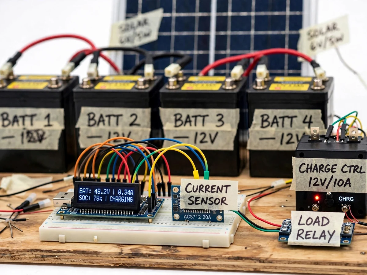
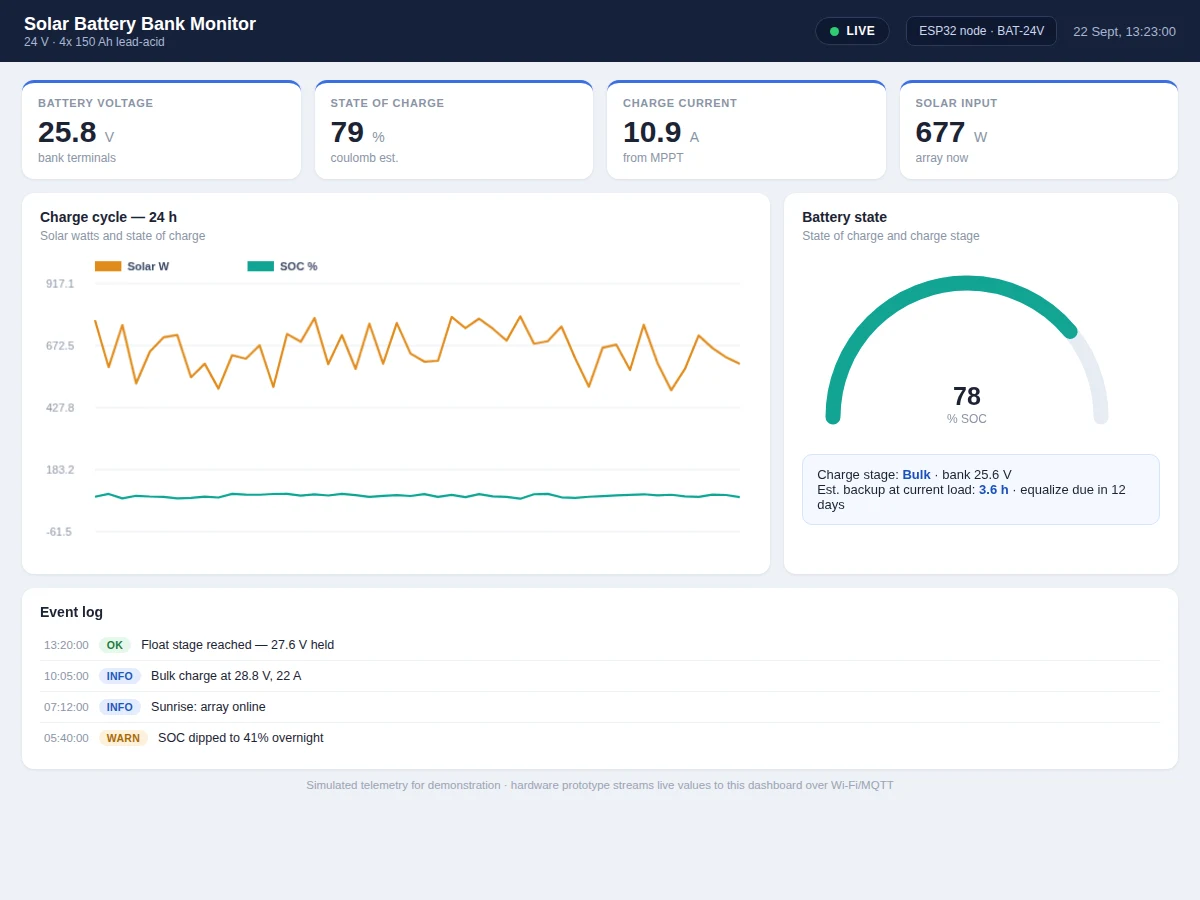
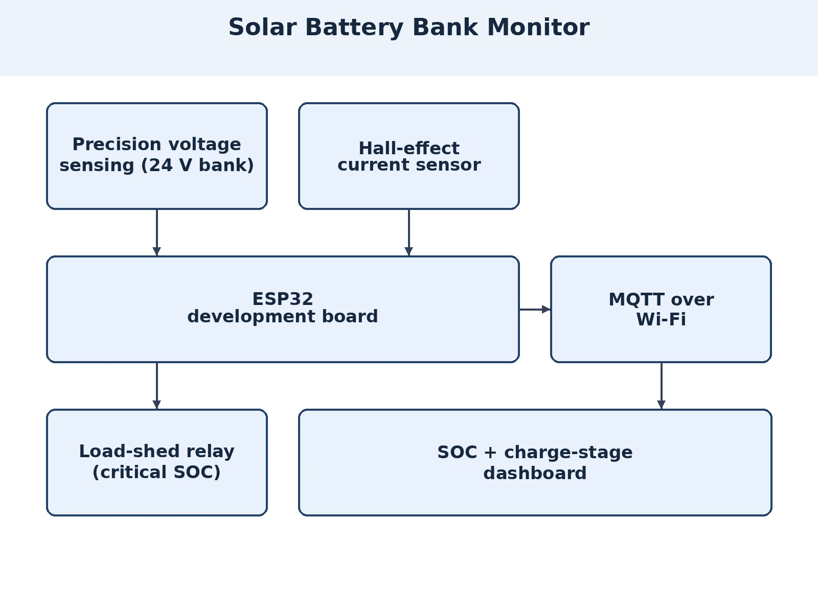
Solar home systems and small institutions run on lead-acid banks that die young — not from age, but from chronic undercharging, deep discharge and nobody watching the state of charge. A voltmeter alone cannot tell you the bank's health because voltage sags under load and recovers at rest. This project builds a proper monitor: a 24 V bank (four 12 V batteries) with a precision voltage divider, a Hall-effect current sensor for charge/discharge current, and solar input measurement at the charge controller. An ESP32 computes state of charge by coulomb counting corrected with rested-voltage, tracks bulk/absorption/float stages, and publishes everything over Wi-Fi via MQTT to a dashboard with SOC gauges, 24-hour charge-cycle graphs and backup-time estimates. The project states the method's limits plainly: coulomb counting drifts and needs periodic full-charge resets, which the firmware performs automatically.
Divides the 24 V bank voltage into the ESP32 ADC range so the bank voltage is measured accurately.
Follow the working sequence
How it works
- The voltage divider, Hall-effect current sensor and solar input tap are wired to the ESP32 on the 24 V bank + solar demonstration rig.
- Firmware samples voltage and current, integrates current over time for coulomb counting, and corrects SOC with rested-voltage lookup.
- Every 10 seconds (design target) the ESP32 publishes voltage, current, SOC, solar watts and charge stage as JSON over Wi-Fi via MQTT.
- The dashboard renders the SOC gauge, charge-cycle graphs and the backup-time estimate from the live stream.
- Charge-stage logic classifies bulk/absorption/float from the voltage and current signatures each cycle.
- When SOC falls below the low threshold, an alert fires; at the critical threshold the load-shed relay opens.
- A detected full charge (float at low current) resets the coulomb counter, bounding long-term drift — the key to usable SOC.
Tech stack:
- ESP32 development board
- 24 V battery bank (4x 12 V, demo)
- Precision voltage divider network
- Hall-effect current sensor (ACS758 class)
- Solar panel + charge controller (demo)
- Relay module (load-shed output)
- MQTT broker + web dashboard
- Arduino IDE (C/C++ firmware)
| Parameter | Value |
|---|---|
| Controller | ESP32, Wi-Fi MQTT telemetry (JSON payloads) |
| Bank | 24 V nominal (4x 12 V lead-acid, demonstration scale) |
| Voltage sensing | Divider network; approximately +/-1% typical (expected) |
| Current sensing | Hall-effect, bidirectional charge/discharge |
| SOC method | Coulomb counting + rested-voltage correction + auto full-charge reset |
| Reporting | 10-second design-target interval; MQTT reconnect with backoff |
| Dashboard | SOC gauge, charge-cycle graphs, stage indicator, backup estimate, alerts |
| Load shed | Relay output at critical SOC (configurable) |
Project features
- [State-of-charge tracking] Coulomb counting with rested-voltage correction and automatic full-charge resets gives a usable SOC figure — far beyond a raw voltmeter.
- [Charge-stage detection] Firmware identifies bulk, absorption and float stages from voltage/current signatures and displays the active stage.
- [Live bank dashboard] SOC gauge, bank voltage, charge/discharge current, solar watts and backup-time estimate, all from live telemetry.
- [Charge-cycle graphs] 24-hour plots of solar input, SOC and current show the full daily cycle for the report's analysis section.
- [Backup-time estimate] Remaining backup hours are estimated from SOC and the recent average load — the number users actually care about.
- [MQTT telemetry] The ESP32 publishes bank readings as JSON over Wi-Fi via MQTT with a design-target 10-second interval.
- [Protection alerts] Low SOC, over-voltage and over-current thresholds raise dashboard alerts; a relay can shed non-critical load at critical SOC.
What is included
- Working solar + battery demonstration rig (bank, panel, controller, sensors, ESP32)
- Complete firmware source (SOC engine, stage detection, MQTT, load-shed)
- Live web dashboard (gauges, charge graphs, backup estimate) demonstrated with the rig
- Circuit and wiring documentation
- Voltage/current calibration procedure against reference meters
- Component list with ratings
- Project report PDF (lead-acid background, SOC methods, charge stages, methodology)
- PPT presentation for final review
- Viva Q&A preparation document (coulomb counting, charge stages, Hall sensing, MQTT)
- Setup and demonstration guide
Limitations & prerequisites
- SOC by coulomb counting drifts between full charges; the auto-reset bounds it, but the figure is an estimate (approximately +/-5-8%, expected), not a laboratory measurement.
- Demonstrated at 24 V demo-bank scale; the method scales but larger banks need re-rated sensing and protection.
- Rested-voltage correction needs genuine rest periods — a continuously cycled bank leans on coulomb counting alone.
- Lead-acid behaviour is assumed; lithium banks need different voltage curves and are listed as future scope.
- Battery terminals and the charge controller carry real energy — assembly follows the supervised build guide.
Frequently Asked Questions
How is state of charge calculated?
By coulomb counting — integrating charge/discharge current over time — corrected with rested-voltage lookup and automatic resets at detected full charge. The report explains why a voltmeter alone is misleading and how the reset bounds long-term drift.
What are the charge stages it detects?
Bulk (constant current, voltage rising), absorption (constant voltage, current tapering) and float (maintenance voltage) — classified from the voltage/current signatures each cycle and shown live on the dashboard.
How accurate is the SOC?
Approximately +/-5-8% (expected) between full-charge resets — honest and usable for backup planning. The manual documents the drift sources and the reset logic that contains them.
What happens at low battery?
A low-SOC alert fires first; at the configurable critical threshold the load-shed relay disconnects non-critical loads to protect the bank from deep discharge.
Can it work with lithium batteries?
The sensing hardware transfers directly, but lithium needs different voltage curves and protection logic — documented as future scope in the report.
Is this project suitable for a final-year project?
Yes — for Electrical Engineering programs. It covers battery sensing, SOC algorithms, charge-stage analysis, MQTT telemetry and protection logic, all strong viva material. Suitable for B.E./B.Tech final-year projects in Electrical Engineering.
Components & software requirements
- ESP32 development board
- 24 V battery bank (4x 12 V, demo)
- Precision voltage divider network
- Hall-effect current sensor (ACS758 class)
- Solar panel + charge controller (demo)
- Relay module (load-shed output)
- MQTT broker + web dashboard
- Arduino IDE (C/C++ firmware)
Delivery information
Built-to-order project. Delivery timeline is shared after order confirmation based on current queue.
Support terms
Complete documentation, setup guide, and viva preparation included. Support for setup and explanation provided.
Download free synopsis (PDF)
Enter your name and WhatsApp number — the synopsis PDF downloads immediately. We may send occasional project updates on WhatsApp; no spam.